Address
304 North Cardinal
St. Dorchester Center, MA 02124
Work Hours
Monday to Friday: 7AM - 7PM
Weekend: 10AM - 5PM
Address
304 North Cardinal
St. Dorchester Center, MA 02124
Work Hours
Monday to Friday: 7AM - 7PM
Weekend: 10AM - 5PM

Wiring a PV combiner box correctly requires precise conductor sizing, proper torque application, and strict NEC 690.15 compliance. A single wiring mistake—undersized conductors, improper polarity, or loose terminations—can cause system failure, fire hazards, or code violations resulting in failed inspections.
This step-by-step guide covers the complete wiring process from pre-installation planning through final testing. You’ll learn conductor sizing calculations per NEC 690.8, terminal torque specifications, grounding requirements per 690.43, and polarity verification methods. We’ll also cover the most common wiring mistakes that cause 80% of combiner box failures.
⚠️ Safety Warning: PV arrays generate voltage whenever light is present. Always cover modules or wire during low-light conditions. Verify zero voltage with a multimeter before touching any conductors. DC voltage above 50V can be lethal.
Essential Hand Tools:
– Calibrated torque wrench (20-400 in-lb range with ±4% accuracy)
– Wire strippers (10-2 AWG capacity)
– Cable cutters for copper/aluminum
– Crimping tool for compression lugs
– Insulated screwdrivers (1000V rated)
– Hacksaw or conduit cutter
Testing Equipment:
– Digital multimeter (600V DC minimum, 0.1V resolution)
– Clamp meter for current measurement
– Insulation tester (megohmmeter, 1000V test voltage)
– Infrared thermometer or thermal camera
– Continuity tester
Safety Equipment:
– Class 0 rubber insulating gloves (1000V rated)
– Arc-rated PPE (NFPA 70E compliant)
– Safety glasses with side shields
– Hard hat for overhead work
– Fall protection if on rooftop
Materials Required:
– Conductors sized per NEC 690.8 (see sizing section)
– Compression or mechanical lugs (UL listed)
– Anti-oxidant compound for aluminum conductors
– Equipment grounding conductors per 690.43
– Conduit and fittings (rigid metal or EMT)
– Weather-resistant labels (UV-rated)
– Wire identification markers
Key Code Requirements for Combiner Box Wiring:
1. Conductor Ampacity (690.8(B)(1)): Size for 125% of short-circuit current after 690.8(A)(1) adjustment
2. Overcurrent Protection (690.9): Fuses or breakers must protect conductors
3. Grounding (690.43): Equipment grounding conductor required for all metal enclosures
4. Polarity (690.15): Maintain consistent positive and negative identification
5. Workmanship (110.12): Professional appearance, proper support and protection
Before starting installation, verify:
– ✅ Single-line diagram showing string connections
– ✅ String voltage and current ratings at STC
– ✅ Module specifications (VOC, ISC, temperature coefficients)
– ✅ Combiner box datasheet with terminal ratings
– ✅ Approved permit and stamped electrical drawings
– ✅ String labeling plan matching field installation
Apply NEC 690.8(A)(1) safety factors:
Isc(adjusted) = Isc(module) × 1.25 × 1.25

Where:
- First 1.25 = Irradiance factor (690.8(A)(1)(1))
- Second 1.25 = Continuous duty factor (690.8(A)(1)(2))
- Total factor = 1.5625
Example Calculation (JA Solar JAM72S20 module):
Module Isc = 13.2A
Isc(adjusted) = 13.2A × 1.5625 = 20.625A per string
From NEC 690.8(B)(1), conductor ampacity must be:
Conductor Ampacity ≥ Isc(adjusted)

For the example:
Required ampacity ≥ 20.625A

From NEC Table 310.16 (75°C column):
- 12 AWG copper = 25A ✅ ACCEPTABLE
- 10 AWG copper = 35A (better for future expansion)
🎯 Pro Tip: Use 10 AWG minimum for all combiner box wiring even if 12 AWG is code-compliant. The cost difference is minimal ($0.15-0.25/foot), but 10 AWG provides better voltage drop performance and future expansion capability.
Verify voltage drop ≤3% per NEC 690.8(B)(1)(b):
Voltage Drop (%) = (2 × K × I × L) / (A × V) × 100

Where:
- K = Conductor resistance (12.9 for copper, 21.2 for aluminum)
- I = Operating current (typically 0.8 × Isc)
- L = One-way conductor length (feet)
- A = Conductor area (circular mils)
- V = System voltage

Example (50-foot run, 10 AWG copper, 600V system):
VD% = (2 × 12.9 × 10.56A × 50) / (10,380 × 600) × 100 = 0.22% ✅
| Module Isc | Adjusted (×1.5625) | Min Copper AWG | Recommended AWG |
|---|---|---|---|
| 8-10A | 12.5-15.6A | 14 AWG | 12 AWG |
| 11-13A | 17.2-20.3A | 12 AWG | 10 AWG |
| 14-16A | 21.9-25.0A | 10 AWG | 8 AWG |
| 17-19A | 26.6-29.7A | 8 AWG | 6 AWG |

Location Requirements:
– Height: 4-6.5 feet per NEC 404.8
– Clearance: 36″ depth, 30″ width per NEC 110.26
– No obstructions requiring ladders or tools
– IP65 rating if outdoor exposed
Installation: Mark holes, drill pilots, install anchors rated for 4× box weight, mount level, torque bolts 25-35 ft-lb.
Sizing per NEC 312.5 (40% fill for 3+ conductors):
Example: 6× 10 AWG = 0.1266 in² → Need 0.3165 in² → Use 3/4" EMT
Entry Steps: Knock out hole, deburr edges, install weatherproof hub, apply thread sealant, torque locknut 40-50 ft-lb.
Stripping: Match lug barrel length (0.5-0.75″), use wire strippers (not knives), inspect for damaged strands, twist stranded wire clockwise, apply anti-oxidant to aluminum only.
⚠️ Critical: Never over-strip. Exposed copper beyond lug creates arc hazard.
Compression Lugs: Insert conductor fully (verify bottomed), position hydraulic crimper at spec location, crimp once (never double-crimp), pull test at 50 lb force for 10 AWG.
Mechanical Lugs: Insert conductor, torque set screws per spec, verify hand pull resistance, re-torque aluminum after 10 minutes.
Color Standards: Red (+), Black (-), Green/bare (ground only—never circuits)
Verification: Measure VOC at string with multimeter, positive probe on positive terminal should show positive voltage. Mark positive with red tape every 3 feet. Document string-to-position mapping.
Connection Sequence: Identify bus position (red=positive), clean surface, apply anti-oxidant if aluminum bus, position lug, hand-tighten, then torque per specification below.
Torque Specifications:
| Conductor Size | Copper Terminal (in-lb) | Aluminum Terminal (in-lb) | Bolt Size |
|---|---|---|---|
| 14-12 AWG | 45-60 | 50-70 | 1/4-20 |
| 10 AWG | 80-100 | 90-110 | 5/16-18 |
| 8 AWG | 140-160 | 160-180 | 3/8-16 |
| 6 AWG | 200-240 | 230-270 | 3/8-16 |
Torquing Best Practices: Use calibrated torque wrench (beam or click-type), apply in smooth motion, re-torque aluminum after 24 hours, document values, mark completed connections with paint pen.
EGC Sizing per NEC 690.43:
– 15A fuses: 14 AWG copper minimum
– 20A fuses: 12 AWG copper minimum
– 30A fuses: 10 AWG copper minimum
Installation: Locate ground bus (green-marked), clean paint from box, install bonding bushing on conduits, connect EGC from bushing to ground bus, torque 40-50 in-lb, bond to grounding electrode, verify <0.5Ω continuity.
💡 Key Insight: Run individual EGCs with each string for redundant ground path per 690.43(B).
Output Sizing: Sum all string Isc(adjusted). Example: 8 strings × 20.6A = 165A → Use 2/0 AWG copper (175A) or 3/0 AWG aluminum.
Main OCPD: Rate at 125% of continuous current. Example: 165A × 1.25 = 206A → Use 225A breaker.
Connection: Verify DC rating, clean busbar, position breaker ensuring full engagement, torque bus bolts 250-300 in-lb, connect output lugs, torque per breaker spec.
Visual Inspection: Verify conductors sized/marked correctly, polarity consistent (red=+, black=-), all connections torqued and marked, no bare copper exposed, grounding complete, fuses installed/rated, labels installed, conduit supported every 3 feet.
Continuity Testing (De-Energized):
– Bus bars: <0.05Ω across each bus, no continuity between + and -
- String circuits: <1.0Ω end-to-end per string
- Ground: <0.5Ω box to electrode, <0.25Ω conduit bondingInsulation Resistance: Short + and – buses together, apply 1000V DC test between shorted buses and ground, minimum 1 MΩ (prefer >5 MΩ), hold 60 seconds, document results.
Polarity Check: Measure voltage at each fuse position—positive terminal should show +VOC relative to negative bus.
Initial Power-Up: Install fuses one at a time starting String 1, measure voltage after each (should equal VOC), measure combined output current during peak sun with clamp meter.
Thermal Imaging: After 2-4 hours operation, scan all terminations. Acceptable <10°C above ambient, investigate >20°C rise, immediate action >30°C.
Acceptance: All string voltages within ±5%, no hotspots >30°C, output current matches calculated ±10%, no ground faults, insulation >1 MΩ.
Problem: Positive and negative conductors swapped, causing parallel strings to create short circuit through combiner box.
Symptoms:
– Blown fuses immediately upon energization
– Zero voltage at output despite modules generating
– Extreme heat at bus bars before fuse blow
Correction:
1. De-energize entire array (cover modules or work at night)
2. Remove all fuses from combiner
3. Verify polarity at each string with multimeter
4. Reverse incorrectly connected conductors
5. Re-test polarity before installing fuses
6. Energize one string at a time while monitoring voltage
Prevention: Always measure and mark polarity at array before pulling conductors.
Problem: Under-torqued terminals creating high-resistance connections that cause heat buildup and eventual failure.
Symptoms:
– Thermal imaging shows hotspots (>40°C) at specific terminals
– Discoloration or melting of conductor insulation
– Intermittent system faults during peak production
– Smell of burning plastic
Correction:
1. De-energize circuit and allow cooling
2. Remove conductor and inspect for heat damage
3. If conductor shows discoloration >1 inch, replace entire run
4. Clean bus and lug contact surfaces
5. Re-terminate with proper torque using calibrated wrench
6. Re-test thermal profile after 24 hours operation
Prevention: Always use calibrated torque wrench. Re-torque aluminum connections after 24 hours.
Problem: Conductors sized for nominal current without applying NEC 690.8 factors, causing code violation and overcurrent trip.
Correction:
– If discovered before energization: Replace with correctly sized conductors
– If discovered during inspection: System will not pass; must rewire
– Calculate required size using Isc × 1.5625 factor
– Verify conductor ampacity from NEC Table 310.16 (75°C column)
Prevention: Always apply both 1.25 factors (1.5625 total) per NEC 690.8(A)(1).
Problem: Equipment grounding conductor omitted or undersized, creating shock hazard and code violation.
Symptoms:
– Tingles when touching metal enclosure
– Ground fault indicator trips
– Failed electrical inspection
– High-resistance ground path (>0.5Ω)
Correction:
1. Install properly sized EGC per NEC 690.43
2. Bond all metal enclosures and conduits
3. Verify <0.5Ω continuity to ground electrode
4. Install bonding bushings on all conduit entries
5. Use green/bare conductor for EGC (never use for circuits)
NEC 690.56 Exterior Label:
PV COMBINER BOX
Max System Voltage: [VOC at Tmin]
Max Operating Current: [Sum Isc × 1.5625]
WARNING: ELECTRIC SHOCK HAZARD - DO NOT DISCONNECT UNDER LOAD
Interior String Labels: String ID (matching array), module type/quantity, VOC and ISC, circuit number.
Conductor ID: Red (+), Black (-), Green/bare (ground), label every 3 feet and terminations.
Commissioning Records: Single-line as-built, string-to-terminal table, torque checklist, insulation test results, thermal imaging, polarity table, photos, manufacturer cut sheets.
Initial (30 Days): Re-torque aluminum connections, thermal scan terminations, check fuse condition, verify enclosure sealing, document hotspots.
Annual: Visual inspection of conductor insulation, torque check 20% sample, full thermal imaging, insulation resistance test (>1 MΩ), clean oxidized bus bars, replace faded labels.
Corrective Actions:
– Hotspot >30°C: De-energize, remove conductor, clean contacts, re-terminate with proper torque, retest after 24 hours
– Insulation <1 MΩ: Check moisture ingress, verify gasket condition, test individual circuits to isolate fault
Size conductors using NEC 690.8: multiply module short-circuit current by 1.5625 (1.25 × 1.25 factors), then select conductor ampacity from Table 310.16 equal to or greater than this value. For example, 13.2A Isc requires 20.6A capacity, so use 12 AWG minimum (25A). Recommended practice is 10 AWG for all combiner wiring to provide margin and better voltage drop performance.
At each string in the array, use a multimeter set to DC voltage. Place the positive (red) probe on the module terminal marked positive, and negative (black) probe on the negative terminal. Reading should show positive voltage (typically 300-600V). If voltage reads negative, your probe connection is reversed. Mark the positive conductor with red tape every 3 feet before pulling through conduit.
Torque specifications vary by wire size and terminal material. For 10 AWG copper terminals, use 80-100 in-lb. Aluminum terminals require 15-20% higher torque (90-110 in-lb) due to cold flow. Always verify manufacturer specifications on the terminal lug or combiner box documentation. Use a calibrated torque wrench (±4% accuracy) and re-torque aluminum connections after 24 hours.
Yes, aluminum conductors are acceptable per NEC when properly sized and terminated. Size aluminum one gauge larger than copper equivalent (10 AWG copper = 8 AWG aluminum). Use only terminals rated “AL/CU” or “AL only”. Apply anti-oxidant compound to all aluminum connections. Re-torque after 24 hours and annually due to aluminum cold flow. Aluminum saves 40-60% material cost on long runs.
Perform thermal imaging inspection at 30 days after commissioning, then annually thereafter. Re-torque aluminum connections at 30 days. Annual visual inspection should check for conductor insulation damage, fuse discoloration, and enclosure seal integrity. Immediate inspection required if monitoring shows unexplained power loss, if fuses blow, or after extreme weather events.
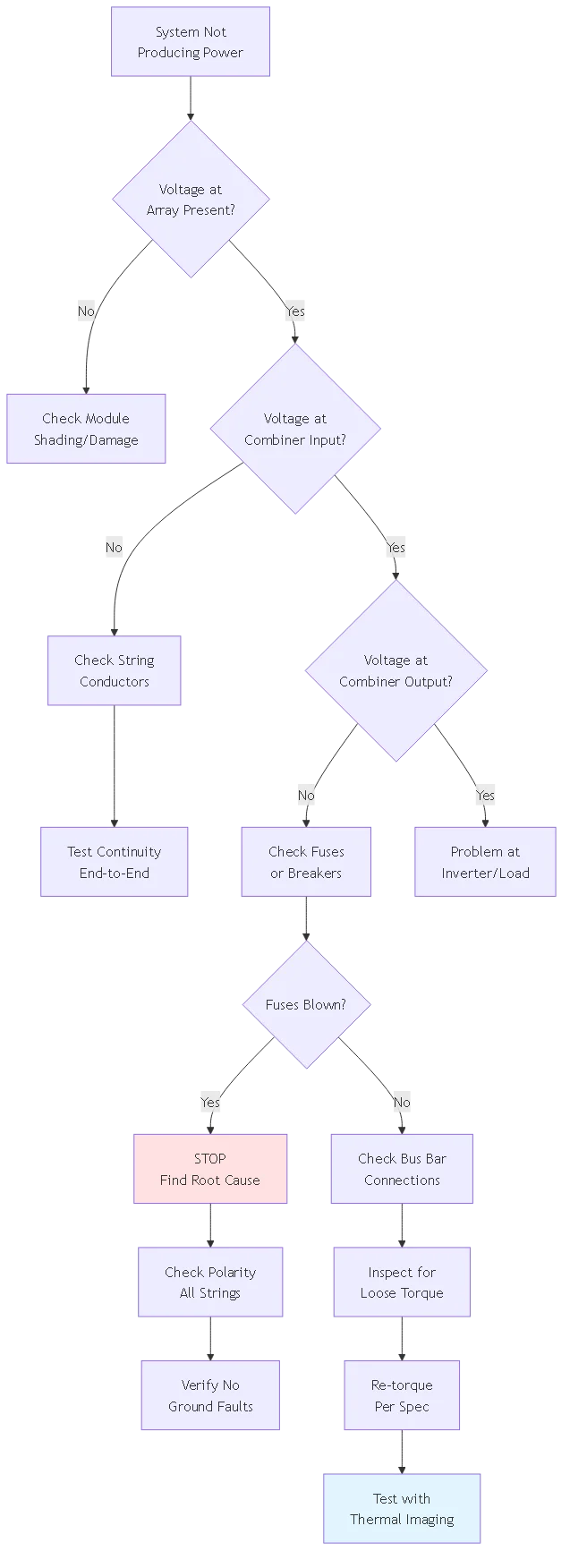
Most common cause (70%) is reversed polarity—positive and negative swapped creating short circuit. Other causes: ground faults (15%), lightning surges (10%), undersized fuses (5%). Always verify polarity with multimeter before energizing. Investigate root cause before replacing blown fuses to prevent repeated failure.
NEC 690.43 requires equipment grounding but does not mandate individual string EGCs. Best practice is to run separate equipment grounding conductor with each string rather than relying on conduit bonding. This provides redundant ground path and better fault current handling. Size EGC per Table 250.122 based on overcurrent device protecting the circuit (typically 12-14 AWG for combiner fuses).
#
Focus Keyword: how to wire a pv combiner box
URL Slug: how-to-wire-pv-combiner-box-guide
Meta Title: How to Wire a PV Combiner Box: NEC 690.15 Step-by-Step Guide
Meta Description: Learn how to wire a pv combiner box with proper torque specs, conductor sizing, and grounding. Complete installation guide with NEC 690.15 compliance and testing procedures.
Content Tier: Tier 3 (Supporting Content)
Conversion Funnel: Top of Funnel (Awareness)
Target Word Count: 2800-4000 words
Target Mermaid Diagrams: 3
Please configure these in Rank Math settings, then delete this box before publishing.
Size conductors using NEC 690.8: multiply module short-circuit current by 1.5625, then select conductor ampacity from Table 310.16 equal to or greater than this value. For 13.2A Isc, use 12 AWG minimum (25A ampacity). Recommended practice is 10 AWG for all combiner wiring to provide margin and better voltage drop performance.
Use a multimeter set to DC voltage at each string. Place the positive probe on the module positive terminal and negative probe on negative terminal. Reading should show positive voltage (300-600V typical). Mark the positive conductor with red tape every 3 feet before pulling through conduit.
For 10 AWG copper terminals, use 80-100 in-lb. Aluminum requires 15-20% higher torque (90-110 in-lb) due to cold flow. Always verify manufacturer specifications. Use calibrated torque wrench and re-torque aluminum connections after 24 hours and annually.
Yes, aluminum is acceptable when properly sized and terminated. Size aluminum one gauge larger than copper (10 AWG copper = 8 AWG aluminum). Use only AL/CU rated terminals, apply anti-oxidant compound, and re-torque after 24 hours due to cold flow. Aluminum saves 40-60% on material costs.
Perform thermal imaging at 30 days after commissioning, then annually. Re-torque aluminum connections at 30 days. Annual visual inspection should check conductor insulation, fuse condition, and enclosure seals. Inspect immediately if monitoring shows power loss or after extreme weather.
Most common cause (70%) is reversed polarity creating short circuit through parallel strings. Other causes: ground faults (15%), lightning surges (10%), undersized fuses (5%). Always verify polarity with multimeter before energizing. Investigate root cause before replacing fuses.
NEC 690.43 requires equipment grounding but not individual string EGCs. Best practice is running separate equipment grounding conductor with each string rather than relying on conduit bonding. This provides redundant ground path and better fault current handling.