Address
304 North Cardinal
St. Dorchester Center, MA 02124
Work Hours
Monday to Friday: 7AM - 7PM
Weekend: 10AM - 5PM
Address
304 North Cardinal
St. Dorchester Center, MA 02124
Work Hours
Monday to Friday: 7AM - 7PM
Weekend: 10AM - 5PM


The IEC 62305 standard series represents the most comprehensive international framework for lightning protection system (LPS) design, superseding numerous national standards and providing unified methodology for protecting structures and systems against lightning effects. For solar installations, this standard offers critical guidance absent from electrical codes like NEC Article 690—addressing direct strike interception, electromagnetic field management, surge protection coordination, and grounding design for the unique challenges photovoltaic systems present.
Published in four parts between 2006-2010 and updated through 2024, IEC 62305 addresses lightning protection holistically: risk assessment determining protection necessity (Part 2), physical protection system design (Part 3), electrical and electronic systems protection (Part 4), and services protection entering structures (Part 1 general principles). Yet field studies reveal only 30-35% of commercial solar installations fully comply with IEC 62305 recommendations—many designers default to minimum NEC requirements unaware that the electrical code addresses shock/fire hazards but not comprehensive lightning damage prevention.
This technical guide explains IEC 62305 application specifically for solar system protection. You’ll learn the four-part standard structure, risk assessment calculations determining protection level requirements, protection zone concept for coordinated surge protection, Lightning Protection System (LPS) classes I-IV with corresponding design parameters, and component selection ensuring coordinated protection from direct strikes through connected electronics. Whether designing utility-scale ground-mount arrays or rooftop commercial installations, IEC 62305 provides the engineering foundation for reliable lightning protection.
💡 Critical Insight: IEC 62305 shifts lightning protection from reactive (repair damage after strikes) to proactive (prevent damage through risk-based design)—calculating acceptable loss probability and engineering protection systems achieving target risk reduction.
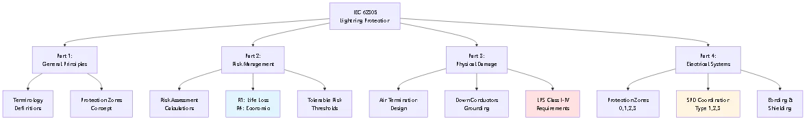
The IEC 62305 series divides lightning protection into four interconnected parts, each addressing specific aspects of comprehensive protection.
Purpose: Establishes fundamental concepts, terminology, and protection requirements applicable to all lightning protection applications.
Key definitions:
Lightning Protection System (LPS): Complete system of air termination, down conductors, grounding electrodes, bonding components, and surge protective devices providing protection against direct strikes and indirect effects.
Protection zone: Three-dimensional space where electromagnetic field from lightning is attenuated to levels safe for protected equipment. Nested zones provide progressively better protection.
Separation distance: Minimum spacing between lightning protection components and protected systems preventing dangerous sparking (side-flash) during strikes.
Lightning protection level (LPL): Classification I-IV defining minimum and maximum lightning current parameters the protection system must handle. Determines rolling sphere radius, mesh size, and component ratings.
Purpose: Provides methodology for calculating lightning risk to structures and determining economic justification for protection systems.
Risk assessment process:
Step 1: Identify risk types
– R1: Risk of loss of human life
– R2: Risk of loss of service to public
– R3: Risk of loss of cultural heritage
– R4: Risk of loss of economic value
Step 2: Calculate risk components
Risk from direct strikes to structure, strikes near structure, strikes to connected services, and strikes near services. Each component includes probability of strike occurrence and consequential loss probability.
Step 3: Determine tolerable risk
IEC 62305-2 Annex A defines tolerable risk levels:
– R1 (life loss): 10⁻⁵ per year (1 in 100,000 chance annually)
– R2 (service loss): 10⁻³ per year
– R4 (economic loss): Determined by economic analysis
Step 4: Compare calculated vs tolerable risk
If calculated risk exceeds tolerable threshold, protection measures required. Standard provides protection measure effectiveness factors, allowing iterative design optimizing cost vs risk reduction.
Solar-specific considerations: Large array footprint increases strike probability (collection area component). Valuable inverter electronics and monitoring systems increase loss magnitude. Remote locations may have limited emergency response, increasing life safety risk from fires.
Purpose: Specifies air termination, down conductor, and grounding electrode design preventing physical damage from direct lightning attachment.
Core requirements:
Air termination placement: Uses rolling sphere method with radius dependent on LPS class (20m for Class I, 60m for Class IV). Any point on structure contacted by rolling sphere requires protection.
Down conductor count and spacing: Minimum two down conductors for structures with perimeter <50m, four conductors for perimeter >50m. Maximum spacing between conductors: 10m for Class I, 25m for Class IV.
Grounding electrode resistance: Target <10Ω for reliable performance. Standard provides calculation methods for various electrode types (rods, rings, foundation electrodes).Bonding requirements: All metallic systems and structural components within structure must bond to LPS preventing dangerous voltage differences during strikes.
Purpose: Addresses surge protection for sensitive electronics—inverters, monitoring systems, SCADA equipment—vulnerable to electromagnetic fields and conducted surges.
Protection zones concept: Divides structure into nested protection zones with decreasing electromagnetic field intensity:
Zone 0: Outside LPS protection, full lightning electromagnetic field
Zone 1: Inside structure with external LPS, reduced field
Zone 2: Inside shielded room or cabinet, further reduced field
Zone 3: Equipment-level shielding, minimal field
SPD coordination: Surge protective devices at zone boundaries provide staged protection. Type 1 SPD at service entrance (Zone 0→1 boundary), Type 2 at distribution panel (Zone 1→2), Type 3 at sensitive equipment (Zone 2→3).
Solar application: DC SPDs required at inverter input, AC SPDs at inverter output. Additional SPDs protect monitoring circuits and communication systems from induced surges.
IEC 62305-3 defines four Lightning Protection Levels corresponding to different protection efficacies and design parameters. Selection depends on risk assessment results and economic considerations.
Class I (Maximum Protection – 98% Efficacy)
Application: Critical facilities, hospitals, structures with explosive materials, irreplaceable cultural heritage, locations with high lightning density (>10 flashes/km²/year).
Design parameters:
– Rolling sphere radius: 20 meters
– Mesh size (horizontal conductors): 5m × 5m maximum
– Protection angle: 25° at h=20m
– Minimum lightning current: 200 kA (captures 99th percentile strikes)
– First stroke peak current: 200 kA
– Specific energy: 10 MJ/Ω
Typical solar applications: Utility-scale installations in high-lightning regions, solar-plus-storage systems with lithium batteries, arrays on hospitals or data centers.
Class II (Enhanced Protection – 95% Efficacy)
Application: Commercial buildings, medium-risk industrial facilities, structures where public gathers, most commercial solar installations.
Design parameters:
– Rolling sphere radius: 30 meters
– Mesh size: 10m × 10m maximum
– Protection angle: 35° at h=20m
– Minimum lightning current: 150 kA
– First stroke peak current: 150 kA
– Specific energy: 5.6 MJ/Ω
Typical solar applications: Commercial rooftop systems 50-500kW, ground-mount community solar, industrial facility arrays.
Class III (Standard Protection – 90% Efficacy)
Application: Standard commercial and industrial structures, residential buildings in moderate-to-high lightning areas, typical solar installations.
Design parameters:
– Rolling sphere radius: 45 meters
– Mesh size: 15m × 15m maximum
– Protection angle: 45° at h=20m
– Minimum lightning current: 100 kA
– First stroke peak current: 100 kA
– Specific energy: 2.5 MJ/Ω
Typical solar applications: Commercial rooftop 10-100kW, residential systems in high-lightning areas, most carport and canopy installations.
Class IV (Basic Protection – 80% Efficacy)
Application: Low-risk structures, agricultural buildings, small residential installations in low-lightning regions (<3 flashes/km²/year).Design parameters:
– Rolling sphere radius: 60 meters
– Mesh size: 20m × 20m maximum
– Protection angle: 55° at h=20m
– Minimum lightning current: 100 kA
– First stroke peak current: 100 kA
– Specific energy: 2.5 MJ/Ω
Typical solar applications: Residential systems <10kW in low-lightning areas, small commercial arrays where economic analysis doesn't justify higher protection.
Factor 1: Strike probability
Calculate annual expected strike frequency:
Nd = Ng × Ae × Cd × 10⁻⁶
Where:
– Ng = Ground flash density (flashes/km²/year from isokeraunic maps)
– Ae = Equivalent collection area of structure
– Cd = Environmental coefficient (1.0 isolated, 0.5 urban)
Example: 100m × 50m array in Ng=6 region:
Ae = (100+6×20) × (50+6×20) = 220 × 170 = 37,400 m² = 0.0374 km²
Nd = 6 × 0.0374 × 0.5 = 0.112 strikes/year (strike every 9 years)
Factor 2: Consequence of failure
– Life safety risk: Requires Class I or II
– High-value equipment (>$500k): Class II minimum
– Standard commercial: Class III acceptable
– Low-value residential: Class IV may suffice
Factor 3: Economic analysis
Annual cost of protection (amortized capital + maintenance) vs expected annual loss:
– If protection cost < 0.1 × expected annual loss: Economically justified
- If protection cost > expected annual loss: Consider lower protection class
| Parameter | Class I | Class II | Class III | Class IV |
|---|---|---|---|---|
| Protection Efficacy | 98% | 95% | 90% | 80% |
| Rolling Sphere (m) | 20 | 30 | 45 | 60 |
| Mesh Size (m) | 5×5 | 10×10 | 15×15 | 20×20 |
| Peak Current (kA) | 200 | 150 | 100 | 100 |
| Typical Solar App | Utility-scale | Commercial | Small commercial | Residential |
🎯 Pro Tip: When selecting between adjacent classes (e.g., Class II vs III), calculate the incremental protection cost—often only 10-20% more material but provides 5% better protection efficacy potentially avoiding one damaging strike over system lifetime.

IEC 62305-4 introduces the protection zone concept—dividing structures into nested volumes with progressively reduced electromagnetic field levels. This enables coordinated surge protection matching sensitivity to field intensity.
Lightning Protection Zone (LPZ) 0A: Volume exposed to direct lightning strikes and full lightning electromagnetic field (LEMP). Air termination system defines boundary between LPZ 0A and interior zones. Threat level: Full lightning current and field.
Lightning Protection Zone (LPZ) 0B: Volume protected against direct strikes but exposed to full or partial LEMP. Typical example: interior of structure with external air termination but no electromagnetic shielding. Threat level: No direct strikes, partial electromagnetic field, full conducted surges on entering services.
Lightning Protection Zone (LPZ) 1: Volume where surge currents limited by SPDs at zone boundary and electromagnetic field attenuated by structure shielding. Metal building skin or grid-style conductors provide shielding. Threat level: Reduced surge magnitude, attenuated electromagnetic field.
Lightning Protection Zone (LPZ) 2+: Volumes with further electromagnetic field reduction and surge limitation. Achieved through interior shielded rooms, metal enclosures, or additional SPD stages. Threat level: Further reduced surges and fields appropriate for sensitive electronics.
Bonding at boundaries: All conductive systems crossing zone boundaries must bond to equipotential bonding bar at the boundary. This includes:
– Power conductors (with SPDs)
– Communication lines (with signal SPDs)
– Metallic pipes and conduits
– Structural steel
– Cable trays and raceways
SPD installation: Surge protective devices install at zone boundaries, protecting against conducted surges on circuits entering higher-protection zones.
Shielding continuity: Electromagnetic shielding must be continuous without gaps larger than λ/10 where λ is wavelength of highest frequency of concern (typically 1 MHz for lightning, λ = 300m, λ/10 = 30m).
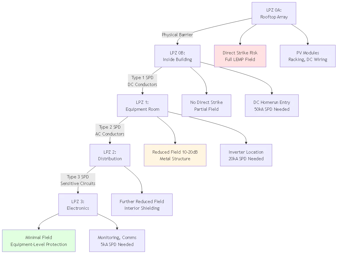
Typical configuration for rooftop commercial array:
LPZ 0A: Rooftop space including PV array, racking, external wiring. Full exposure to direct strikes and electromagnetic field.
LPZ 0B boundary: Building roof/walls providing physical shelter but minimal electromagnetic shielding.
LPZ 0B→1 transition: DC homerun conduit entry into building. Install Type 1 DC SPD at this boundary protecting against surges on DC conductors.
LPZ 1: Interior equipment room housing inverter, AC distribution, monitoring equipment. Metal building structure provides electromagnetic shielding reducing field by 10-20 dB.
LPZ 1→2 transition: AC output from inverter entering main electrical panel. Install Type 2 AC SPD at this boundary.
LPZ 2: Main electrical distribution area. Additional field reduction from interior walls, conduits.
LPZ 2→3 transition: Circuits feeding sensitive monitoring, communications, or control equipment. Install Type 3 SPDs at equipment inputs.
Protection strategy: Each zone transition incorporates SPD appropriate for threat level, progressively limiting surge magnitudes to levels tolerable by equipment in the protected zone.
Surge protective device selection must consider protection zone location, connected equipment withstand voltage, and coordination with upstream/downstream SPDs.
Type 1 SPD (Class I test per IEC 61643-11)
Application: LPZ 0→1 boundary, service entrance, locations exposed to partial lightning current (direct strike to nearby service line, induction from nearby strikes).
Test requirement: 10/350 μs waveform, 25-100 kA impulse current. This long-duration waveform simulates actual lightning current.
Protection parameters:
– Nominal discharge current (In): 25-50 kA (8/20 μs)
– Impulse current (Iimp): 25-100 kA (10/350 μs)
– Voltage protection level (Up): Typically 2.5-4.0 kV for 1000V DC systems
– Follow current interruption: Must extinguish AC fault current after SPD conduction
Solar application: DC SPD at combiner box input from strings, DC SPD at inverter DC input, AC SPD at inverter AC output (service entrance equivalent).
Type 2 SPD (Class II test)
Application: LPZ 1→2 boundary, distribution panel, sub-panel locations where Type 1 SPD provides upstream protection against direct effects.
Test requirement: 8/20 μs waveform, 20-40 kA discharge current. Shorter duration than lightning but sufficient for induced surges and switching transients.
Protection parameters:
– Nominal discharge current (In): 20-40 kA
– Maximum discharge current (Imax): 40-80 kA
– Voltage protection level (Up): 2.0-3.0 kV for 1000V systems
– Response time: <25 nsSolar application: AC SPD at main distribution panel (if Type 1 at service entrance), DC SPD at inverter if Type 1 at combiner, monitoring circuit protection.
Type 3 SPD (Class III test)
Application: LPZ 2→3 boundary, equipment-level protection for sensitive electronics requiring lower voltage protection than Type 1/2 provide.
Test requirement: Combination wave (1.2/50 μs voltage, 8/20 μs current), lower energy than Type 1/2.
Protection parameters:
– Nominal discharge current (In): 5-10 kA
– Voltage protection level (Up): 1.0-1.5 kV for 1000V systems
– Response time: <25 ns
- Fine protection for equipment with low surge immunitySolar application: Monitoring equipment inputs, communication circuits (Ethernet, RS-485), control circuits to motor drives or trackers.
Upstream coordination: Ensure Type 1 SPD withstands energy that would otherwise reach Type 2/3 devices. Type 1 must clamp surge below Type 2 maximum rating.
Selectivity: If fault occurs, only the SPD nearest the source should operate, leaving upstream protection intact. Achieved through different clamping voltages and response times.
Backup protection: If Type 1 fails (from exceeded rating or end-of-life), fuse or disconnect must clear fault before damaging protected equipment or causing fire.
Installation separation: IEC 62305-4 recommends minimum 10-meter conductor length between SPD types (or 5m with decoupling inductance) preventing interaction during surge events.
System parameters:
– Array: 100kW rooftop, 300 modules, 10 strings
– Voc: 950V DC maximum
– Location: Ng = 5 flashes/km²/year
– Protection class: LPS Class II
SPD selection:
String combiner (LPZ 0A→0B):
– Type 1 DC SPD required (partial lightning current exposure)
– Iimp: 25 kA minimum (Class II requirement)
– UCPV: 1000V minimum (Voc × 1.2 factor)
– Up: <3.5 kV (inverter withstand typically 6 kV)
- Quantity: 1 per string = 10 SPDsInverter DC input (LPZ 0B→1):
– Type 1 or Type 2 DC SPD depending on distance from combiner
– If <10m from combiner: Type 2 acceptable (In = 40 kA)
- If >10m: Type 1 required (Iimp = 25 kA)
– Up: <2.5 kV (lower than combiner SPD for coordination)Inverter AC output (LPZ 1→2):
– Type 2 AC SPD (service entrance equivalent)
– In: 40 kA per phase
– Voltage: 480V three-phase system
– Up: <2.0 kV L-N, <3.5 kV L-PE
IEC 62305-2 provides detailed risk assessment formulas. Practical application for solar installation:
For 50m × 30m commercial building with 75kW rooftop array:
RA: Risk from direct strike to structure (array on roof)
RB: Risk from strike near structure (induced surges)
RC: Risk from strike to utility line (conducted surges)
RD: Risk from strike near utility line (induced on service)
Total risk R = RA + RB + RC + RD
Direct strike to structure (NA):
Collection area Ae = (L+6H) × (W+6H)
– Building: 50m × 30m × 10m height
– Ae = (50+60) × (30+60) = 110 × 90 = 9,900 m² = 0.0099 km²
– NA = Ng × Ae × Cd = 5 × 0.0099 × 0.5 = 0.025 strikes/year
Strike near structure (NB):
NB = Ng × (250m radius circle area – Ae)
NB = 5 × (0.196 – 0.0099) = 0.93 strikes/year (affects electronics via induced surges)
Strike to connected service (NC):
Assumes 100m utility line, overhead construction
Ac = 1000 × 100 = 100,000 m² = 0.1 km²
NC = Ng × Ac × Ce = 5 × 0.1 × 1.0 = 0.50 strikes/year
For each risk component, multiply strike probability by loss probability factors from IEC 62305-2 tables.
Example for RA (direct strike):
RA = NA × PA × LA
Where:
– PA = probability of damage (depends on LPS class, construction, surge protection)
– LA = consequent loss (life loss, equipment damage, service loss)
Without LPS: PA = 1.0 (unprotected), LA = 0.01 (office building, limited occupancy)
RA = 0.025 × 1.0 × 0.01 = 0.00025
With Class III LPS: PA = 0.1 (90% protection efficiency), same LA
RA = 0.025 × 0.1 × 0.01 = 0.000025
Tolerable risk for life loss: RT = 10⁻⁵ = 0.00001
Without protection: R ≈ 0.00025 (combined all components)
R > RT → Protection required
With Class III LPS + Type 1/2 SPDs: R ≈ 0.000008
R < RT → Adequate protectionConclusion: Class III protection system economically justified, reduces risk below tolerable threshold.

Problem: Installing Type 2 SPD at service entrance (LPZ 0→1 boundary) instead of required Type 1. Type 2 devices lack 10/350 μs withstand capability, failing during direct strike current exposure.
Common scenarios:
– Using residential-grade AC SPDs (Type 3) at commercial service entrance
– DC SPD at combiner box rated only for 8/20 μs, not 10/350 μs
– Mixing SPD types without verifying energy coordination
Correction: Verify SPD test class matches IEC 61643-11 requirements for installation location. Type 1 mandatory at LPZ 0→1, Type 2 at LPZ 1→2, Type 3 at LPZ 2→3. Check manufacturer datasheets for test waveform (10/350 or 8/20 μs).
Problem: Applying rolling sphere method without accounting for protection class selection. Using 60m radius (Class IV) when Class II required based on risk assessment.
Common scenarios:
– Defaulting to NEC requirements (essentially Class IV) for commercial installations requiring Class II
– Not performing risk assessment to determine appropriate protection level
– Using protection angle method beyond its valid range (h/H > 0.6)
Correction: Conduct IEC 62305-2 risk assessment determining required protection class. Apply corresponding rolling sphere radius: 20m (Class I), 30m (Class II), 45m (Class III), 60m (Class IV). Document risk calculation justifying class selection.
Problem: Failing to bond all metallic systems at protection zone boundaries. Unbonded systems develop dangerous voltage differences during strikes, causing arcing and equipment damage.
Common scenarios:
– DC conduit entering building not bonded to grounding system
– Module racking not bonded to building structure
– Communication cables lacking signal line SPDs at zone boundary
– Separate electrical and lightning protection grounds without bonding
Correction: Install equipotential bonding bar at each zone boundary. Bond all conductive systems crossing boundary: power conductors (with SPDs), signal lines (with signal SPDs), metallic pipes/conduits, structural elements. Use minimum 6 AWG bonding conductors, compression terminals, and anti-oxidant compound.
Problem: Single ground rod attempting to serve entire lightning protection system. IEC 62305-3 requires multiple distributed electrodes for effective energy dissipation.
Common scenarios:
– Relying on electrical service ground rod (one 8-foot rod)
– Not installing grounding ring for large structures
– Ground rods spaced too closely (overlapping resistance spheres)
Correction: Minimum two ground rods for structures with perimeter <50m, four rods for >50m. Space rods ≥2× rod length apart (16 feet minimum for 8-foot rods). Implement grounding ring for arrays exceeding 50kW. Target <10Ω combined resistance verified by fall-of-potential testing.
Problem: Installing protection components without documented design basis or class designation. Prevents verification of code compliance and limits liability protection.
Common scenarios:
– Designer specifies “lightning protection per NEC” (NEC doesn’t define protection classes)
– Contractor uses available components without engineering analysis
– No as-built drawings showing air termination coverage or SPD locations
Correction: Prepare IEC 62305-compliant design documentation including: risk assessment calculation determining required protection class, rolling sphere analysis showing air termination coverage, SPD coordination plan with type and location specified, grounding system layout with resistance calculations. Provide to building authority for permit approval and maintain for insurance certification.
IEC 62305 compliance can be verified through third-party certification providing insurance discounts and demonstrating due diligence.
TÜV (Technischer Überwachungsverein): German inspection association offering lightning protection system certification per IEC 62305. Reviews design documentation and inspects installed systems. Certification valid 3-5 years with annual re-inspection.
UL (Underwriters Laboratories): North American certification organization. While UL 96A addresses lightning protection, it predates IEC 62305. New installations increasingly reference IEC rather than UL standards.
National Lightning Safety Institute (NLSI): US-based organization providing lightning protection design review and installation inspection. Issues certificates of compliance for IEC 62305-compliant systems.
Design review: Examiner verifies risk assessment calculation, protection class selection justification, rolling sphere coverage analysis, SPD coordination plan, grounding design calculations.
Installation inspection: Inspector verifies conductor sizes meet minimums, air termination covers all exposure points per rolling sphere, grounding resistance <10Ω, bonding continuity <0.2Ω, SPD test class matches installation location.Documentation: Certification file includes design calculations, as-built drawings, test results, maintenance schedule. Required for insurance underwriting and building authority approval in some jurisdictions.
Premium reduction: Many commercial property insurers offer 5-15% premium reduction for certified lightning protection systems. Savings often recover certification cost in 2-3 years.
Claim support: Certified systems demonstrate due diligence. If lightning damage occurs despite protection, certification supports claim that system was properly designed/installed, shifting liability to equipment manufacturer rather than installer/owner.
Required coverage: Some insurers require IEC 62305 certification for solar installations exceeding $500k value or in high-lightning regions (Ng >8). Without certification, coverage may be denied or limited.
IEC 62305 is the international standard series for lightning protection system design published by the International Electrotechnical Commission. It consists of four parts covering general principles, risk assessment, physical protection, and electrical system protection. For solar systems, IEC 62305 provides comprehensive methodology absent from electrical codes like NEC Article 690—addressing direct strike interception through air termination design, surge protection coordination for DC and AC circuits, grounding system requirements for energy dissipation, and electromagnetic field management protecting sensitive electronics. The standard introduces the protection zone concept dividing installations into nested volumes with progressively reduced lightning threat, enabling coordinated SPD selection. It defines four Lightning Protection System classes (I-IV) corresponding to 98%-80% protection efficacy, allowing designers to match protection level to risk assessment results. While not legally mandatory in most jurisdictions, IEC 62305 compliance demonstrates engineering best practice, supports insurance underwriting, and increasingly required for building permits on commercial solar installations exceeding 50kW.
LPS Class I (98% protection, 20m rolling sphere) applies to critical facilities and high-lightning regions. Class II (95% protection, 30m sphere) suits commercial buildings and most commercial solar 50-500kW. Class III (90% protection, 45m sphere) covers standard commercial and residential systems in moderate lightning areas. Class IV (80% protection, 60m sphere) applies to low-risk structures in minimal lightning regions. Selection depends on IEC 62305-2 risk assessment calculating strike probability and consequence. Residential systems <10kW typically use Class III or IV unless high lightning density (>5 flashes/km²/year) or life safety concerns dictate Class II. Commercial installations 10-100kW generally require Class II or III depending on occupancy, equipment value, and lightning exposure. Utility-scale systems >500kW typically specify Class II minimum due to large footprint increasing strike probability and high equipment concentration. Each class defines corresponding design parameters: Class II uses 30m rolling sphere for air termination coverage, 10m×10m mesh maximum, 150kA minimum protection current. Higher classes cost 10-20% more than adjacent lower class but provide 5% better protection efficacy.
IEC 62305-2 provides risk assessment methodology calculating strike probability and comparing to tolerable risk thresholds. Process involves: (1) Calculate expected annual strike frequency using local ground flash density (Ng), structure collection area, and environmental factors. Example: 100m×50m array in Ng=5 region expects 0.11 strikes/year. (2) Determine risk type—R1 for life loss, R4 for economic loss. Each has tolerable threshold: R1 = 10⁻⁵ (1 in 100,000 annually), R4 determined by cost-benefit analysis. (3) Calculate total risk from four components: direct strikes to structure, strikes near structure, strikes to entering services, strikes near services. Each component multiplies strike probability by damage probability and consequent loss. (4) Compare calculated risk to tolerable threshold. If R > RT, protection required; if R < RT, protection optional but may be economically justified. For most commercial solar installations, risk assessment shows protection economically beneficial—cost of LPS system ($5,000-25,000) significantly less than expected annual loss from unprotected strikes. Residential systems may fall below mandatory threshold but protection still advisable in lightning-prone regions.
The protection zone concept divides structures into nested volumes (LPZ 0, 1, 2, 3) with decreasing electromagnetic field intensity from lightning. LPZ 0A (outside, full exposure) transitions to LPZ 0B (inside structure, partial field) then LPZ 1 (reduced field via building shielding) and higher zones with further field reduction. At each zone boundary, install appropriate surge protective devices and bonding components. Implementation for typical commercial solar: LPZ 0A contains rooftop array exposed to direct strikes. Building roof creates LPZ 0B boundary—install Type 1 DC SPD where DC conductors enter building (40-50kA discharge current, 10/350μs test waveform). Interior equipment room becomes LPZ 1 with metal structure providing 10-20dB field attenuation—install Type 2 AC SPD at inverter output (20-40kA, 8/20μs test). Sensitive monitoring equipment occupies LPZ 2 with additional shielding—install Type 3 SPDs on communication circuits (5-10kA). Bond all metallic systems (conduits, pipes, structural steel) crossing each boundary to equipotential busbar at that boundary. This staged approach progressively limits surge magnitudes from 100kA+ at LPZ 0 to <5kA at sensitive equipment, matching protection to threat level.
SPD type selection depends on location within protection zone structure and test class per IEC 61643-11. Type 1 (Class I test) required at LPZ 0→1 boundary where partial lightning current exposure possible—service entrance, DC homerun entry from rooftop array, connections to overhead utility lines. Must withstand 10/350μs test waveform (25-100kA impulse current) simulating actual lightning. Type 2 (Class II test) installs at LPZ 1→2 boundary for distribution panels, inverter locations with upstream Type 1 protection, sub-panels. Tested to 8/20μs waveform (20-40kA) adequate for induced surges after Type 1 has limited direct effects. Type 3 (Class III test) provides equipment-level protection at LPZ 2→3 for sensitive electronics requiring lower clamping voltage—monitoring systems, communication equipment, control circuits. Energy coordination requires voltage protection level of downstream SPD (Up,n+1) less than withstand voltage of protected equipment (Uw,n). Install 10-meter minimum conductor length between SPD types or use decoupling inductance preventing interaction. Common mistake: installing residential Type 3 devices at commercial service entrance requiring Type 1. Verify manufacturer datasheet specifies correct test waveform for intended location.
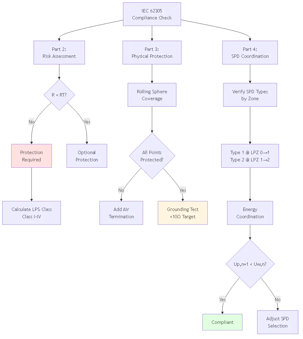
Compliance testing involves three phases: design verification, installation inspection, and performance testing. Design verification reviews risk assessment calculations ensuring protection class selection justified, rolling sphere analysis confirming all exposure points covered, SPD coordination verifying energy ratings match zone requirements. Inspection during installation checks conductor sizes (2 AWG copper minimum for lightning protection, 6 AWG for bonding), air termination placement, bonding connections have star washers penetrating coatings, torque specifications met (7-9 N⋅m module frames, 15-20 N⋅m ground clamps). Performance testing after completion measures grounding resistance using fall-of-potential method (target <10Ω), verifies bonding continuity between components (<0.2Ω resistance), confirms SPD installation per manufacturer requirements. Testing frequency: initial commissioning, annually during maintenance, after known lightning strikes, after any system modifications affecting protection. Engage third-party certification body (TÜV, NLSI) for formal compliance certificate supporting insurance underwriting—costs $2,000-8,000 depending on system size but provides premium discounts recovering cost in 2-3 years. Document all testing with photos, resistance measurements, and SPD specifications for building authority approval and future reference.
IEC 62305 compliance typically adds 15-30% to lightning protection costs compared to minimum NEC requirements, but this incremental investment provides substantially better protection and insurance benefits. Example commercial 100kW rooftop system: Basic NEC compliance (essentially Class IV protection) costs $8,000-12,000 including grounding electrodes, equipment bonding, and Type 2 SPDs. IEC 62305 Class II system costs $12,000-18,000—requires additional air termination devices for 30m rolling sphere coverage vs 60m NEC equivalent, Type 1 SPDs at LPZ boundaries vs Type 2 only, larger grounding conductors (2 AWG vs 6 AWG), and more electrodes achieving <10Ω vs <25Ω. However, benefits include: 95% vs 80% protection efficacy potentially avoiding one damaging strike over 25-year system life ($50,000+ loss), 5-15% insurance premium reduction ($500-2,000 annual savings), improved permit approval and inspection pass rates, third-party certification supporting liability defense. For utility-scale installations >500kW, IEC compliance becomes economically compelling—incremental cost $0.02-0.04/watt adds $10,000-40,000 to $1-2M total system cost (0.5-2% premium) while reducing lightning damage risk by 15-18 percentage points. Residential systems see higher percentage cost impact (30-40%) but absolute dollars remain modest ($1,500-3,000 incremental for Class III compliance).
IEC 62305 transforms lightning protection from reactive damage response to proactive risk management—calculating acceptable loss probability and engineering protection systems achieving target risk reduction. The four-part standard series provides comprehensive methodology addressing direct strike interception (Part 3), electromagnetic field management (Part 4), surge protection coordination (Part 4), and economic justification (Part 2) specific to solar installations’ unique challenges.
Key Takeaways:
1. Risk assessment determines protection requirements—IEC 62305-2 calculation methods evaluate strike probability, equipment value, and life safety considerations, producing quantitative justification for protection class selection rather than arbitrary code minimums.
2. Protection zone concept enables coordinated surge protection—dividing structure into nested LPZ volumes with staged SPD selection (Type 1 at LPZ 0→1, Type 2 at 1→2, Type 3 at 2→3) progressively limits surges matching equipment withstand capabilities.
3. LPS class selection balances cost vs efficacy—Class I (98%, $0.04/W) through Class IV (80%, $0.01/W) allows designers to optimize protection investment against lightning exposure, with most commercial solar requiring Class II or III.
4. Physical and electrical protection must coordinate—air termination captures strikes, down conductors route current safely, grounding dissipates energy, and SPDs protect electronics from residual surges—all four elements required for comprehensive protection, individual components insufficient.
5. Third-party certification provides economic benefits—$2,000-8,000 certification investment often recovers in 2-3 years through insurance premium reduction (5-15%) while demonstrating due diligence supporting liability defense after damage events.
Investment in IEC 62305-compliant protection—incremental 15-30% above basic code requirements—costs far less than unprotected lightning damage typically exceeding $25,000 residential, $50,000 commercial, and $500,000+ utility-scale per event. The standard provides engineering foundation transforming lightning protection from insurance gamble to calculated risk management.
Related Resources:
– Solar Panel Lightning Protection Grounding Methods
– Lightning Protection Air Termination Design
– DC SPD Selection and Coordination
Ready to implement IEC 62305-compliant lightning protection for your solar installation? Contact our lightning protection engineering team for comprehensive risk assessment, protection class determination, LPS design with rolling sphere analysis, SPD coordination planning, and certification support. We provide turnkey solutions from initial risk calculation through third-party certification and insurance approval.
Last Updated: February 2026
Author: SYNODE Technical Team
Reviewed by: Lightning Protection Standards Department
Focus Keyword: lightning protection for solar system
URL Slug: lightning-protection-solar-systems-iec-62305-standards
Meta Title: Lightning Protection for Solar Systems: IEC 62305 Standards
Meta Description: Master lightning protection for solar system design with IEC 62305 standards: protection zones, lightning risk assessment, LPS classes, component selection, and compliance methods.
Content Tier: Tier 3 (Supporting Content)
Conversion Funnel: Top of Funnel (Awareness)
Target Word Count: 2800-4000 words
Target Mermaid Diagrams: 3
Please configure these in Rank Math settings, then delete this box before publishing.
IEC 62305 is the international standard series for lightning protection system design covering general principles, risk assessment, physical protection, and electrical system protection. For solar systems, it provides comprehensive methodology addressing direct strike interception, surge protection coordination for DC and AC circuits, grounding requirements, and electromagnetic field management. The standard introduces the protection zone concept and defines four LPS classes (I-IV) corresponding to 98%-80% protection efficacy. While not legally mandatory in most jurisdictions, IEC 62305 compliance demonstrates engineering best practice and increasingly required for commercial solar installations exceeding 50kW.
LPS Class I (98% protection, 20m rolling sphere) applies to critical facilities. Class II (95% protection, 30m sphere) suits commercial solar 50-500kW. Class III (90% protection, 45m sphere) covers standard commercial and residential systems. Class IV (80% protection, 60m sphere) applies to low-risk structures. Selection depends on IEC 62305-2 risk assessment. Residential systems <10kW typically use Class III or IV. Commercial 10-100kW generally require Class II or III. Utility-scale >500kW typically specify Class II minimum. Each class defines design parameters with higher classes costing 10-20% more but providing 5% better protection efficacy.
IEC 62305-2 risk assessment involves: Calculate expected annual strike frequency using local ground flash density, structure collection area, and environmental factors. Determine risk type—R1 for life loss (threshold 10⁻⁵), R4 for economic loss. Calculate total risk from direct strikes, nearby strikes, and service strikes. Compare calculated risk to tolerable threshold. If R > RT, protection required. For most commercial solar, risk assessment shows protection economically beneficial—LPS system cost ($5,000-25,000) significantly less than expected annual loss from unprotected strikes.
Protection zones divide structures into nested volumes (LPZ 0, 1, 2, 3) with decreasing electromagnetic field intensity. LPZ 0A (outside, full exposure) transitions to LPZ 0B (inside structure) then LPZ 1 (reduced field via building shielding) and higher zones. At each boundary, install appropriate SPDs and bonding. For commercial solar: LPZ 0A contains rooftop array. Install Type 1 DC SPD where conductors enter building (LPZ 0B→1). Interior equipment room becomes LPZ 1—install Type 2 AC SPD at inverter output (LPZ 1→2). Sensitive monitoring in LPZ 2—install Type 3 SPDs. Bond all metallic systems crossing boundaries.
Type 1 (Class I test, 10/350μs, 25-100kA) required at LPZ 0→1 boundary—service entrance, DC homerun entry from rooftop. Type 2 (Class II test, 8/20μs, 20-40kA) installs at LPZ 1→2—distribution panels, inverter locations with upstream Type 1. Type 3 (Class III test) provides equipment-level protection at LPZ 2→3 for sensitive electronics. Energy coordination requires downstream SPD voltage protection level less than equipment withstand voltage. Install 10-meter minimum conductor length between SPD types. Verify manufacturer datasheet specifies correct test waveform for intended location.
Compliance testing involves design verification, installation inspection, and performance testing. Design verification reviews risk assessment calculations, rolling sphere analysis, SPD coordination. Inspection checks conductor sizes (2 AWG copper minimum), air termination placement, bonding connections with star washers, torque specifications. Performance testing measures grounding resistance using fall-of-potential method (target <10Ω), verifies bonding continuity (<0.2Ω). Test at commissioning, annually, after lightning strikes, after modifications. Third-party certification (TÜV, NLSI) costs $2,000-8,000 but provides insurance premium discounts recovering cost in 2-3 years.
IEC 62305 compliance adds 15-30% to lightning protection costs vs minimum NEC but provides substantially better protection. Commercial 100kW example: Basic NEC costs $8,000-12,000, IEC Class II costs $12,000-18,000. Benefits include 95% vs 80% protection efficacy, 5-15% insurance premium reduction ($500-2,000 annual savings), improved permit approval. For utility-scale >500kW, incremental cost $0.02-0.04/watt adds $10,000-40,000 (0.5-2% of total) while reducing lightning damage risk by 15-18 percentage points. Investment recovers through avoided damage and insurance savings.