Address
304 North Cardinal
St. Dorchester Center, MA 02124
Work Hours
Monday to Friday: 7AM - 7PM
Weekend: 10AM - 5PM
Address
304 North Cardinal
St. Dorchester Center, MA 02124
Work Hours
Monday to Friday: 7AM - 7PM
Weekend: 10AM - 5PM

Solar panel electrical safety represents one of the most misunderstood aspects of photovoltaic systems. Unlike AC electrical systems that de-energize when disconnected from the grid, PV arrays generate dangerous DC voltage whenever sunlight strikes the modules—even during installation, maintenance, or emergency response. This “always-on” characteristic creates unique shock and fire hazards that have contributed to over 12,000 reported incidents since 2015, including 47 fatalities among installers and first responders.
The National Fire Protection Association (NFPA) reports that electrical failures cause 65% of solar system fires, with arc faults accounting for 42% and ground faults 23%. Meanwhile, OSHA data shows electrical shock remains the leading cause of solar installer fatalities, with 78% involving energized DC circuits during maintenance or troubleshooting. These statistics underscore a critical reality: solar panel electrical safety requires specialized knowledge beyond traditional AC electrical work.
This comprehensive guide explains the two primary electrical hazards in PV systems—shock and fire—and provides practical prevention strategies for installers, facility managers, and emergency responders. You’ll learn DC voltage characteristics that make solar different from AC systems, lockout/tagout procedures specifically for “always-energized” arrays, personal protective equipment (PPE) requirements, and emergency response protocols. Whether installing your first residential system or managing utility-scale solar farms, understanding these safety principles protects lives and assets.
💡 Critical Insight: The transition from thinking “disconnect = de-energized” (AC mindset) to “sunlight = energized” (DC reality) represents the most important mental shift for anyone working with or around solar installations.
Direct current electricity from solar panels behaves fundamentally differently than alternating current from the utility grid. These differences create unique hazards requiring specialized safety protocols.
Current pathway persistence: AC current reverses polarity 60 times per second (60Hz), causing muscle contractions that often “throw” victims away from the energized conductor. DC current maintains constant polarity, causing sustained muscle contraction that “locks” victims onto conductors—making self-release nearly impossible.
Arc sustainability: AC arcs naturally extinguish at current zero-crossing twice per cycle. DC arcs have no zero-crossing, sustaining indefinitely once initiated. A 600V DC arc burns continuously at 5000°F+ until current is interrupted by circuit breaker or conductor failure.
Voltage accumulation: Series-connected PV modules create cumulative voltage—a 20-module string at 40V per module produces 800V DC. This voltage exists across the entire string whenever sunlight is present, with no “off” switch until the sun sets or modules are physically covered.
Traditional electrical safety assumption: De-energize circuit, verify zero voltage, then work safely. This approach fails for PV systems.
Solar reality: Module voltage appears instantly when sunlight contacts cells. A single 400W module generates 40-50V DC in bright sunlight—enough to deliver lethal shock if contacted across the chest (hand-to-hand pathway through heart).
Implication: Every connector termination, junction box opening, or troubleshooting procedure on the DC side occurs on energized circuits. Standard lockout/tagout procedures designed for AC equipment provide false security for solar work.
Human perception of electrical current varies with voltage:
Below 50V DC: “Let-go” threshold—most people can release grip if shocked. Still dangerous if current path crosses heart.
50-120V DC: Sustained muscular contraction possible. Self-release difficult. Residential PV strings typically operate in this range (10-20 modules).
120-600V DC: High shock risk. Commercial rooftop systems operate here (20-30 module strings). Severe burns and cardiac effects likely.
Above 600V DC: Immediate life-threatening shock. Utility-scale systems often exceed 1000V DC (30+ module strings). Arc flash hazard adds thermal injury risk.
Critical understanding: Even “low-voltage” residential systems at 120V DC can kill under the right conditions—wet hands, jewelry creating conductive path, or contact points on either side of the heart.
Preventing electrical shock in solar installations requires layered protection: engineering controls, administrative procedures, and personal protective equipment.
Rapid shutdown systems: NEC 690.12 requires rapid shutdown (RSD) that reduces conductor voltage to ≤80V within 10 seconds of activation. This engineering control represents the most effective shock prevention technology.
Implementation approaches:
– Module-level power electronics (MLPE) that shut down individual modules
– String-level disconnects that isolate array sections
– Transmitter-based systems commanding module shutdown via wireless/powerline signals
Effectiveness: RSD reduces shock voltage from 600-1000V to <80V, moving from "immediately life-threatening" to "survivable with injury" range.Touch-safe connectors: MC4 and similar locking connectors require deliberate two-hand disengagement, preventing accidental disconnection that exposes live terminals.
Insulated conductor systems: Use sunlight-resistant insulation rated for maximum system voltage plus 600V margin. THWN-2 or USE-2 cable types provide dual-layer insulation protecting against abrasion and UV degradation.
Voltage verification before every task: Never assume a circuit is de-energized. Use properly-rated DC voltage tester (CAT III or CAT IV) to verify zero voltage before touching conductors.
Procedure:
1. Test voltage tester on known live source to verify function
2. Test PV circuit at expected voltage points
3. If voltage reads zero, re-test tester on live source to verify still functional
4. Only after three-point verification can conductors be considered de-energized
Cover arrays during work: Physically blocking sunlight de-energizes modules when disconnects alone cannot. Use opaque tarps secured against wind, covering entire array surface.
Implementation challenges:
– Large arrays (>50kW) require extensive tarping—time-consuming and labor-intensive
– Wind can lift tarps, re-energizing circuits unexpectedly
– Partial covering still leaves uncovered sections energized
Best for: Residential/small commercial during module replacement or junction box repairs.
Traditional LOTO procedures lock disconnects in the “off” position and tag to prevent re-energization. Solar systems require modified procedures acknowledging that DC circuits remain energized even with disconnects open.
Modified LOTO procedure:
Step 1: Notify affected personnel of maintenance activity and expected duration.
Step 2: Identify all energy sources:
– AC utility connection (can be locked out conventionally)
– DC array (remains energized whenever sun is present)
– Energy storage systems (batteries remain energized regardless of sun)
Step 3: De-energize controllable sources:
– Open AC disconnect, apply LOTO device and tag
– Open DC disconnect, apply LOTO device and tag
– Isolate battery systems, apply LOTO
Step 4: Verify zero energy:
– Test AC circuits for zero voltage ✅
– Test DC circuits—voltage still present ⚠️
– Tag DC circuits: “WARNING: ENERGIZED BY SUNLIGHT”
Step 5: Implement additional controls:
– Cover array with opaque tarps if working on DC circuits
– Use insulated tools rated for DC voltage
– Wear appropriate PPE (see next section)
– Maintain 18-inch approach distance from exposed conductors
Step 6: Work execution with continuous awareness of energization risk.
Step 7: Post-work verification:
– Remove tools, materials, and personnel
– Remove tarps (DC circuits now fully energized)
– Remove LOTO devices
– Restore system to operation
⚠️ Warning: Never work alone on energized PV systems. Two-person minimum crew ensures someone can render aid if shock occurs. One person maintains 10-foot distance while second works, avoiding concurrent shock to both personnel.
Working on or near energized PV systems requires specific PPE beyond standard construction safety gear.
Class 00 rubber insulating gloves: Rated for 500V AC/750V DC maximum. Minimum requirement for residential solar work (120-600V systems).
Class 0 rubber insulating gloves: Rated for 1000V AC/1500V DC. Required for commercial systems exceeding 600V.
Glove inspection protocol:
– Pre-use air test—inflate gloves, roll to check for leaks
– Check for punctures, tears, embedded foreign objects
– Verify manufacturer test date—retest every 6 months
– Discard gloves showing damage or age-related deterioration
Insulated tools: Use tools with non-conductive handles rated for maximum system voltage. Standard tools with plastic grips are NOT adequate—must be specifically designed and tested for electrical work.
Tool requirements:
– Screwdrivers, pliers, wrenches with 1000V+ insulation rating
– “VDE certified” or “IEC 60900” marked tools
– Intact insulation with no cracks or wear-through to metal
Arc-flash events release intense thermal energy. Standard cotton work clothes provide minimal protection—synthetic fabrics melt into skin, causing severe burns.
Arc-rated PPE requirements:
ATPV rating: Arc Thermal Performance Value measured in calories/cm². Higher numbers = greater protection.
Residential systems (<10kW): Minimum 4 cal/cm² arc-rated shirt + pants (ATPV 4).
Commercial systems (10-100kW): 8 cal/cm² arc-rated suit (ATPV 8).
Utility-scale (>100kW): 12-40 cal/cm² depending on available fault current.
Arc-rated PPE includes:
– Flame-resistant shirts and pants (no exposed skin between)
– Arc-rated face shield (8+ cal/cm²)
– Leather work gloves over rubber insulating gloves
– Leather work boots (steel-toe required)
What arc-rated PPE does NOT include:
– Standard cotton clothing (ignites at arc temperatures)
– Synthetic athletic wear (melts at 300-400°F)
– Non-rated safety glasses (melt/shatter in arc flash)
Non-conductive safety glasses: Impact-rated (Z87+) with non-conductive frames. Metal frames create shock path if contacted with live conductors.
Arc-rated face shield: For work on energized equipment >50V. Must cover entire face and wrap around sides. Minimum 8 cal/cm² rating.
Warning: Standard polycarbonate face shields melt in arc flash. Only use shields specifically rated and labeled for arc flash protection.
| PPE Item | Residential (<600V DC) | Commercial (600-1000V DC) | Utility (>1000V DC) |
|---|---|---|---|
| Insulating Gloves | Class 00 (500V) | Class 0 (1000V) | Class 1 (7500V) |
| Arc-Rated Clothing | 4 cal/cm² | 8 cal/cm² | 12-40 cal/cm² |
| Face Shield | 8 cal/cm² | 12 cal/cm² | 20+ cal/cm² |
| Insulated Tools | 1000V rated | 1000V rated | 1000V rated |
🎯 Pro Tip: PPE costs $500-1500 per worker for residential solar work, $1500-3000 for commercial/utility. This investment saves lives—budget PPE as mandatory project cost, not optional expense.
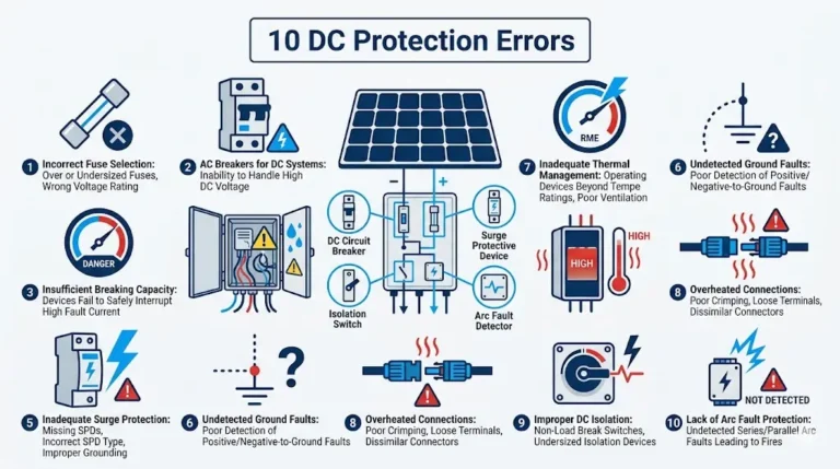
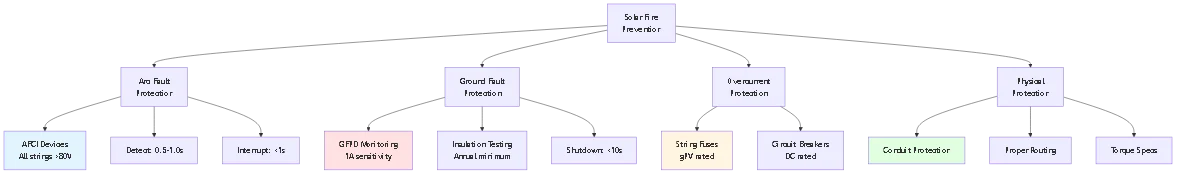
Electrical fires in solar installations originate from two primary mechanisms: arc faults and ground faults. Understanding these failure modes enables effective prevention.
Arc fault definition: Unintended electrical discharge through air, typically caused by damaged insulation, loose connections, or conductor breaks.
Why arc faults cause fires:
– Arc temperature: 5000-10,000°F (hotter than surface of sun)
– Sustained energy: DC arcs burn continuously until interrupted
– Ignition time: 0.5-2 seconds to ignite nearby combustibles
– Common combustibles: Roof membranes, wire insulation, junction box components
Primary arc fault causes in PV systems:
Damaged MC4 connectors (38%): Improper crimp, contaminated contacts, or UV-degraded locking mechanism creating high-resistance connection. Resistance generates heat, carbonizes plastic, initiates arc.
Rodent damage (27%): Squirrels, rats chewing through conductor insulation under arrays, exposing copper. Module weight shifting can press damaged conductors together, creating arc.
Module junction box failures (18%): Bypass diode failures, cracked solder joints, or moisture infiltration creating conductive paths inside module junction boxes.
Installation damage (12%): Conductors pinched during rail installation, wire nuts used instead of compression connectors (vibration loosens over time), inadequate torque on terminals.
Use listed components only: MC4 connectors must be genuine or listed-compatible. Counterfeit connectors cause 40% of connector-related arc faults.
Proper installation technique:
– Crimp MC4 pins with manufacturer-specified tool and die
– Audible “click” when mating connectors (verifies locking)
– Pull-test every connection—should withstand 50+ pounds force
– Torque lugs to specification (typically 7-9 N⋅m for combiner terminals)
Arc fault circuit interrupters (AFCI): Required by NEC 690.11 for DC circuits >80V. AFCI devices detect arc signatures and interrupt circuits within 0.5-1.0 seconds, preventing fire ignition.
Implementation: Most modern inverters include integrated AFCI. String combiner boxes may require standalone AFCI devices for each string.
Ground fault mechanism: Insulation breakdown allows current leakage from DC conductors to grounded module frames or mounting structure. If fault current exceeds 1-2 amps, resistive heating ignites insulation.
Why ground faults cause fires:
– Sustained current flow through insulation (carbonizes, smolders)
– Resistance at fault point generates heat (P = I²R)
– No overcurrent protection—current below fuse/breaker rating
– Can persist for days/weeks before ignition
Ground fault causes:
Insulation degradation (45%): UV exposure, thermal cycling, moisture infiltration over 5-10 years.
Installation damage (35%): Conductors abraded against sharp metal edges, pinched by cable ties, or routed without protection through conduit entries.
Module defects (12%): Manufacturing defects causing internal shorts between cells and frame.
Maintenance errors (8%): Loose junction box covers allowing moisture infiltration, damaged insulation during module replacement.
Ground fault protection devices (GFPD): Monitor current balance between positive and negative DC conductors. Imbalance >1A indicates ground fault, triggering inverter shutdown.
Required by: NEC 690.41 for grounded PV arrays on structures.
Annual insulation resistance testing: Use megohmmeter to measure resistance between DC conductors and ground. Minimum 1MΩ for systems <50kW, 2MΩ for larger systems.Test procedure:
1. Disconnect inverter (open DC disconnect)
2. Measure insulation resistance at multiple points (combiner, homerun, module)
3. Compare to baseline measurements from installation
4. Investigate any reading <2MΩ or >20% decline from baseline
⚠️ Important: Ground fault protection does NOT prevent arc faults, and AFCI does NOT prevent ground faults. Both protection types are required for comprehensive fire prevention.
Despite prevention efforts, electrical emergencies occur. Proper response procedures minimize injury severity and property damage.
If someone is being shocked by PV system:
DO NOT touch the victim—you will also be shocked. DC current causes muscular lock-up preventing self-release.
Immediate actions:
1. Activate rapid shutdown if system equipped (reduces voltage)
2. Cover array with tarps if accessible (de-energizes DC circuits)
3. If neither option available, use non-conductive object (wooden broom handle, plastic pipe) to break victim’s contact with energized conductor
4. Call 911 immediately once victim is separated from energy source
Medical response:
– Check breathing and pulse
– Initiate CPR if no pulse (DC shock can stop heart)
– Place victim in recovery position if breathing/pulse present
– Monitor for shock symptoms until EMS arrives
– Inform EMS of electrical shock (requires cardiac monitoring)
Do NOT assume low voltage is safe: A 120V DC residential system can cause cardiac arrest if current path crosses the heart.
Solar-related electrical fires require special considerations for firefighters:
Unique hazards:
– DC circuits remain energized even after AC utility disconnection
– Water stream creates electrical path from roof to ground personnel
– Rapid shutdown may not function if fire damages control circuits
– Module glass can shatter from thermal shock, projecting shards
Firefighter safety protocol:
1. Assume all solar equipment remains energized—even at night (batteries)
2. Do NOT apply water directly to array—fog pattern only from 10+ feet distance
3. De-energize only after activating rapid shutdown AND covering array
4. Cut conductors only after verifying zero voltage with rated tester
5. Maintain 10-foot approach distance from all DC equipment
Building occupant response:
– Evacuate immediately—don’t attempt to fight electrical fires
– Close doors/windows to contain fire (if safe to do so)
– Alert 911 that structure has solar panels (critical information)
– Inform firefighters of DC disconnect location
– Stay clear—solar arrays can propel burning material during failure
Arc flash events: Explosive release of energy when short circuit occurs. Blast pressure, thermal energy, and molten metal can cause severe injuries.
If arc flash occurs:
1. Immediately evacuate blast radius (10-foot minimum)
2. Do NOT re-approach equipment—secondary arcs can occur
3. Check for injuries: burns (thermal + electrical), blast trauma, vision damage
4. Call 911 if injuries present
5. Treat burns with cool (not cold) water until EMS arrives
6. Do NOT remove adhered clothing—can remove skin layers
Arc flash prevention during maintenance:
– Calculate incident energy level for equipment being serviced
– Wear appropriate arc-rated PPE for calculated energy level
– Use remote operation (racking circuit breakers from distance) when possible
– Establish arc flash boundary—only qualified workers in rated PPE enter
Problem: Assuming disconnected circuits are de-energized without testing, leading to shock when contacting “dead” conductors.
Common scenarios:
– Trusting someone else verified zero voltage
– Assuming nighttime work means no voltage (moonlight/streetlights produce voltage)
– Not testing voltage detector before and after use (missed failed tester)
Correction: Three-point voltage verification every time: (1) Test detector on known live source, (2) Test circuit being worked, (3) Re-test detector on live source. Only proceed if all three tests succeed.
Problem: AC circuit breakers, fuses, or disconnect switches used in DC circuits. These devices rely on AC zero-crossing to extinguish arcs—ineffective for DC, leading to breaker failure and fire.
Common scenarios:
– Standard residential AC breakers in DC combiner boxes
– AC-rated wire nuts on DC strings (vibration loosens over time)
– Indoor-rated AC disconnects used for outdoor DC service entrance
Correction: Verify all DC components are DC-rated and listed for photovoltaic applications. Look for “DC” voltage rating on nameplate and UL listing (UL 489, UL 1741).
Problem: Using residential-grade PPE (Class 00 gloves, 4 cal/cm² clothing) on commercial systems exceeding 600V, providing inadequate protection.
Common scenarios:
– Single PPE kit used for all jobs regardless of voltage
– Assuming higher-voltage systems just need “more caution” not better PPE
– Using aged PPE past manufacturer-recommended life (insulation degrades)
Correction: Match PPE to system voltage per NFPA 70E tables. Residential (<600V): Class 00 gloves, 4 cal/cm². Commercial (600-1000V): Class 0 gloves, 8 cal/cm². Replace PPE every 3 years regardless of apparent condition.
Problem: Solo work on energized PV systems means no one can render aid if shock occurs. DC-induced muscular lock-up prevents self-rescue and calling for help.
Common scenarios:
– Quick troubleshooting “that will only take 5 minutes”
– Cost-cutting by sending single technician
– Solo residential installers working without backup
Correction: Two-person minimum for any work on energized circuits >50V. Second person maintains 10-foot distance while observing, ready to activate rapid shutdown or use non-conductive separation tool if shock occurs.
Problem: Failing to perform annual insulation testing allows ground faults to develop undetected. These faults can smolder for weeks before igniting visible fire.
Common scenarios:
– Assuming GFPD monitoring replaces need for resistance testing
– Not budgeting for annual testing as maintenance cost
– Treating ground fault alarms as nuisances, resetting without investigation
Correction: Annual insulation resistance testing using 500V or 1000V megohmmeter. Document readings, compare to baseline. Investigate any reading <2MΩ or >20% decline. Budget $200-500 for professional testing of residential systems.
Proper training transforms safety knowledge into consistent safe behavior. Multiple certification paths address different roles in solar installations.
OSHA 10-Hour Construction: Entry-level safety training covering fall protection, electrical hazards, PPE. Not PV-specific but establishes baseline.
OSHA 30-Hour Construction: Supervisory-level training. Required for crew leads and site managers on commercial projects.
OSHA 1910.269 (Electrical Power Generation): Applies to utility-scale solar (>1MW). Covers high-voltage safety, approach distances, grounding procedures.
OSHA 1926 Subpart S (Electrical): Construction electrical safety standards. Covers wiring methods, GFCI, PPE selection.
NFPA 70E Standard: Consensus standard for electrical safety in the workplace. Not a code but widely adopted as industry best practice.
Qualified person definition: Person trained and knowledgeable about electrical hazards, proper PPE selection, and safe work procedures. NFPA 70E requires documented training.
Training topics:
– Arc flash hazard analysis and PPE selection
– Approach boundaries (limited, restricted, prohibited)
– Lockout/tagout procedures
– Test equipment selection and use
– Emergency response
Certification: No official NFPA 70E certification exists. Training providers issue certificates of completion for 3-day courses. Annual refresher training recommended.
NABCEP Solar Safety Course: Comprehensive online course covering PV-specific electrical hazards. Recommended for all solar installers regardless of experience.
IREC Solar Installation Professional (SIP): Entry-level credential including safety module. Prerequisite for many installer jobs.
OSHA/NIOSH Electrical Safety and Arc Flash Training: Specialized arc flash training program. Critical for commercial/utility solar workers.
NEC 110.16: Requires field-applied arc flash warning labels on equipment. Implies employer must conduct arc flash hazard analysis.
OSHA General Duty Clause: Requires employers provide safe workplace free from recognized hazards. Lack of PV-specific safety training constitutes recognized hazard.
Recommended employer training program:
– New hire: 8-hour PV electrical safety orientation before site work
– Quarterly: Safety toolbox talks on specific hazards (arc flash, working at heights)
– Annual: 4-hour refresher + practical demonstrations
– After incidents: Root cause analysis + training on corrective actions
Documentation: Maintain training records for all employees. OSHA inspections following injuries routinely request training documentation.
A single 400W solar module produces 40-50V DC in bright sunlight—enough to cause painful shock but typically not lethal for a healthy adult with dry hands. However, danger increases exponentially in series-connected strings. A residential system with 10 modules produces 400-500V DC, and commercial systems reach 600-1000V DC. At these voltages, electric shock can cause cardiac arrest if current crosses the chest (hand-to-hand or hand-to-foot contact). The unique danger of solar DC voltage is it appears whenever sunlight contacts modules—there’s no “off” switch. Even disconnecting from the grid leaves DC circuits energized. Opening junction boxes, disconnecting cables, or troubleshooting requires working on live circuits unless arrays are physically covered with opaque tarps. Additionally, DC current causes sustained muscular contraction preventing victim self-release, unlike AC which often throws victims clear. Always treat solar DC circuits as energized and dangerous regardless of time of day or disconnect status.
Yes—solar panels cause approximately 1 in every 10,000 installations to experience electrical fire, totaling over 1,000 reported fires annually in the US. The primary fire mechanisms are arc faults and ground faults. Arc faults occur when damaged insulation, loose connections, or broken conductors create electrical arcs burning at 5000-10,000°F. Common causes include rodent damage to wiring, improper MC4 connector installation, and UV-degraded cable insulation. Ground faults happen when insulation breaks down, allowing current to leak from DC conductors to grounded metal frames. This current causes resistive heating that smolders and eventually ignites. Prevention requires both Arc Fault Circuit Interrupters (AFCI) and Ground Fault Protection Devices (GFPD), mandated by NEC 690.11 and 690.41 respectively. AFCI detects arc signatures and interrupts circuits within 1 second, while GFPD monitors insulation resistance and shuts down when leakage exceeds 1-2 amps. Annual insulation resistance testing catches degradation before it progresses to fire. Proper installation using listed components, correct torque specifications, and adequate conduit protection reduces fire risk by 85%.
Solar work requires voltage-rated electrical PPE beyond standard construction safety gear. For residential systems (<600V DC), minimum PPE includes Class 00 rubber insulating gloves rated for 500V AC/750V DC, arc-rated clothing (4 cal/cm² minimum), non-conductive safety glasses, and insulated tools rated for 1000V. Commercial systems (600-1000V) require Class 0 gloves rated for 1000V and 8 cal/cm² arc-rated suits. Utility-scale systems (>1000V) need Class 1 gloves and 12-40 cal/cm² protection depending on available fault current. All rubber gloves require leather protectors and pre-use inspection including air test by inflating and checking for leaks. Arc-rated clothing must completely cover exposed skin—standard cotton or synthetic clothing melts or ignites in arc flash. Non-conductive safety glasses prevent shock through metal frames if contacted with live conductors. Insulated tools must be VDE-certified or IEC 60900 marked, not standard plastic-grip tools. Face shields (8+ cal/cm²) are required when working on energized equipment. Cost ranges $500-1500 per worker for residential kit, $1500-3000 for commercial/utility. PPE has limited lifespan—gloves require testing every 6 months, clothing every 3 years regardless of apparent condition.
Solar panels cannot be “turned off” in the conventional sense—they generate voltage whenever sunlight contacts the cells, regardless of disconnect positions or grid connection status. This fundamental misunderstanding causes most solar electrical injuries. The only ways to de-energize solar DC circuits are: (1) Physically cover the array with opaque tarps blocking all sunlight, then verify zero voltage with properly-rated DC tester, (2) Activate rapid shutdown system (if installed) reducing voltage to ≤80V within 10 seconds, (3) Wait until night when no sunlight is present—though moonlight and streetlights can still generate 5-20V. Opening the DC disconnect does NOT de-energize conductors between disconnect and array—these remain at full string voltage. Opening AC disconnect does NOT affect DC side—arrays still energized. The proper verification procedure is three-point test: test your voltage tester on known live source to confirm function, test PV circuit (should read expected voltage), then re-test tester on live source to confirm it didn’t fail. Only if circuits read zero and tester functions both before and after can you proceed assuming de-energized status. Never assume—always test.
First responders face unique hazards at structures with solar installations. Critical information: (1) Solar arrays remain energized even after utility disconnection—cutting power at service panel does not de-energize DC circuits on roof, (2) Water conducts electricity—direct water streams on arrays create shock path from roof to ground personnel, only use fog pattern from 10+ feet distance, (3) Rapid shutdown systems (if present) reduce but don’t eliminate voltage—even “shut down” systems may have 80V present, enough to cause injury, (4) Module glass can shatter from thermal shock, projecting sharp fragments, (5) DC arcs burn continuously unlike AC arcs—don’t assume fire self-extinguishes. Recommended protocols: maintain 10-foot approach distance from all solar equipment, locate DC disconnect (typically labeled and near service entrance), activate rapid shutdown if equipped, cover arrays with tarps if safe to access, inform incident command of solar presence (affects ventilation and tactics). Most fire departments now use “solar placard” systems—red stickers near service entrance indicating solar installation. Some systems include emergency responder sheets detailing equipment locations. Firefighters should NOT attempt to cut DC conductors even if de-energized per disconnect—verify zero voltage with rated tester first. Treat all solar equipment as energized until proven otherwise through proper voltage testing procedures.
Annual professional inspections are recommended minimum for residential systems, semi-annual for commercial installations. Inspections should include: (1) Insulation resistance testing using 500V or 1000V megohmmeter—readings below 2MΩ indicate degradation requiring investigation, (2) Torque verification of all accessible bolted connections—thermal cycling loosens connections over time creating arc fault risk, (3) Visual inspection of cables for damage, abrasion, or UV degradation, (4) MC4 connector examination for cracks, corrosion, or incomplete latching, (5) Junction box inspection for moisture, burn marks, or failed bypass diodes, (6) AFCI/GFPD function test verifying protection devices respond correctly, (7) Infrared thermal scan identifying hotspots indicating high resistance connections (optional but recommended). After severe weather events—hail, high winds, heavy snow—immediate inspection warranted checking for physical damage that could create electrical hazards. Systems in coastal environments require more frequent inspection (quarterly) due to accelerated corrosion from salt exposure. Budget $200-500 for professional residential inspection, $1,000-3,000 commercial. DIY monthly inspections checking for visual damage supplement professional testing but cannot replace megohmmeter testing requiring specialized equipment. Document all inspections with photos and test results—insurance claims often require maintenance records.
Legal requirements vary by jurisdiction, but most areas require: (1) State-licensed electrician designation (journeyman or master), (2) Electrical contractor license for business operation, (3) Local permit for each installation. Some states require specific solar contractor licenses in addition to electrical license. NABCEP (North American Board of Certified Energy Practitioners) PV Installation Professional certification is industry-recognized credential demonstrating competence but is not legally required in most jurisdictions. However, many utilities, incentive programs, and customers require NABCEP certification. OSHA training (10-hour or 30-hour construction) is not certification but demonstrates safety knowledge—increasingly required by general contractors and commercial building owners. Some jurisdictions require fire marshal approval for rooftop installations exceeding certain sizes. Liability insurance typically requires documented training even if not legally mandated. Recommended pathway: obtain state electrical license, complete NABCEP associate training, gain 1-2 years installation experience under supervision, pursue NABCEP PVIP certification. Continuing education requirements vary by state but typically 4-8 hours annually for license maintenance. Always verify local jurisdiction requirements—working without proper licensure risks fines ($500-5,000), permit denial, and insurance claim rejection if accidents occur.
Solar panel electrical safety represents a specialized discipline distinct from traditional AC electrical work. The “always-on” nature of photovoltaic systems, sustained DC arcs, and cumulative string voltages create unique shock and fire hazards requiring modified safety procedures, specialized PPE, and comprehensive training beyond standard electrical practices.
Key Takeaways:
1. DC circuits remain energized whenever sunlight is present—lockout/tagout procedures must acknowledge this reality rather than assuming disconnection equals de-energization. Physical array covering or rapid shutdown systems provide the only reliable de-energization methods.
2. Voltage-rated PPE is mandatory, not optional—Class 00/0 rubber insulating gloves, arc-rated clothing (4-40 cal/cm² depending on system size), and insulated tools prevent the majority of electrical injuries. Standard construction PPE is inadequate for energized solar work.
3. Arc faults and ground faults cause 65% of solar fires—AFCI and GFPD protection devices are required by NEC but effectiveness depends on proper installation and annual verification testing. Prevention through quality components and correct installation eliminates 85% of fire risk.
4. Two-person minimum for energized work—DC-induced muscular contraction prevents self-rescue from electrical shock. Second person maintaining safe distance can activate rapid shutdown or use non-conductive separation tools to break victim contact with energized conductors.
5. Professional training and certification demonstrate competence—NABCEP, NFPA 70E, and OSHA training provide essential knowledge, but hands-on experience under qualified supervision remains irreplaceable for developing safe work habits that prevent incidents.
The solar industry’s safety record continues improving as installers adopt PV-specific procedures recognizing fundamental differences between DC solar and AC electrical systems. Investment in proper PPE ($500-3,000 per worker), annual safety training (8-16 hours), and professional equipment testing ($200-500 annually residential) costs far less than the $2-5 million average liability settlement for electrical fatalities. Treat every PV DC circuit as energized and dangerous until proven otherwise through proper voltage verification—this mindset shift prevents the 78% of installer fatalities involving “assumed de-energized” circuits.
Related Resources:
– DC Circuit Breaker Safety and Selection
– Solar PV System Protection Best Practices
– Lightning Protection for Solar Installations
Ready to implement comprehensive electrical safety for your solar installation? Contact our technical safety team for site-specific hazard analysis, PPE recommendations, training program development, and safety equipment procurement. We provide OSHA-compliant safety plans, arc flash incident energy calculations, and ongoing safety consultation ensuring your team returns home safely every day.
Last Updated: March 2026
Author: SYNODE Technical Team
Reviewed by: Safety Engineering Department
Focus Keyword: solar panel electrical safety
URL Slug: solar-panel-electrical-safety-shock-fire-prevention
Meta Title: Solar Panel Electrical Safety: Shock & Fire Prevention
Meta Description: Essential solar panel electrical safety guide: DC shock prevention, arc fault fire risks, lockout/tagout procedures, PPE requirements, and emergency response for safe PV installations.
Content Tier: Tier 2 (Standard Content)
Conversion Funnel: Bottom of Funnel (Decision)
Target Word Count: 2800-4000 words
Target Mermaid Diagrams: 3
Please configure these in Rank Math settings, then delete this box before publishing.
A single 400W solar module produces 40-50V DC in bright sunlight—enough to cause painful shock but typically not lethal. However, danger increases exponentially in series-connected strings. A residential system with 10 modules produces 400-500V DC, and commercial systems reach 600-1000V DC. At these voltages, electric shock can cause cardiac arrest if current crosses the chest. The unique danger of solar DC voltage is it appears whenever sunlight contacts modules—there’s no ‘off’ switch. DC current causes sustained muscular contraction preventing victim self-release, unlike AC which often throws victims clear.
Yes—solar panels cause approximately 1 in every 10,000 installations to experience electrical fire. The primary fire mechanisms are arc faults and ground faults. Arc faults occur when damaged insulation or loose connections create electrical arcs burning at 5000-10,000°F. Ground faults happen when insulation breaks down, allowing current leakage causing resistive heating. Prevention requires Arc Fault Circuit Interrupters (AFCI) and Ground Fault Protection Devices (GFPD), mandated by NEC. Annual insulation resistance testing and proper installation reduce fire risk by 85%.
Solar work requires voltage-rated electrical PPE beyond standard construction safety gear. For residential systems (<600V DC), minimum PPE includes Class 00 rubber insulating gloves rated for 500V AC/750V DC, arc-rated clothing (4 cal/cm² minimum), non-conductive safety glasses, and insulated tools rated for 1000V. Commercial systems require Class 0 gloves and 8 cal/cm² arc-rated suits. All rubber gloves require leather protectors and pre-use inspection. Cost ranges $500-1500 per worker for residential kit, $1500-3000 for commercial/utility systems.
Solar panels cannot be ‘turned off’ conventionally—they generate voltage whenever sunlight contacts the cells. The only de-energization methods are: physically cover the array with opaque tarps, activate rapid shutdown system reducing voltage to ≤80V, or wait until night. Opening disconnects does NOT de-energize conductors between disconnect and array. Proper verification is three-point test: test voltage tester on known live source, test PV circuit, re-test tester on live source. Only if circuits read zero and tester functions both times can you proceed.
First responders must know: solar arrays remain energized even after utility disconnection, water conducts electricity so only use fog pattern from 10+ feet distance, rapid shutdown systems reduce but don’t eliminate voltage, module glass can shatter from thermal shock, and DC arcs burn continuously. Maintain 10-foot approach distance, locate DC disconnect, activate rapid shutdown if equipped, cover arrays with tarps if safe. Treat all solar equipment as energized until proven otherwise through proper voltage testing.
Annual professional inspections are recommended minimum for residential, semi-annual for commercial. Inspections should include insulation resistance testing using megohmmeter (readings below 2MΩ indicate degradation), torque verification of connections, visual cable inspection, MC4 connector examination, junction box inspection, AFCI/GFPD function testing, and infrared thermal scanning. Coastal environments require quarterly inspection due to salt corrosion. Budget $200-500 for professional residential inspection, $1,000-3,000 commercial. Document all inspections—insurance claims often require maintenance records.
Most jurisdictions require state-licensed electrician designation (journeyman or master) and electrical contractor license. Some states require specific solar contractor licenses. NABCEP PV Installation Professional certification demonstrates competence but is not legally required in most areas—however many utilities and customers require it. OSHA training (10-hour or 30-hour construction) demonstrates safety knowledge. Recommended pathway: obtain state electrical license, complete NABCEP associate training, gain 1-2 years supervised experience, pursue NABCEP PVIP certification. Always verify local jurisdiction requirements.