Address
304 North Cardinal
St. Dorchester Center, MA 02124
Work Hours
Monday to Friday: 7AM - 7PM
Weekend: 10AM - 5PM
Address
304 North Cardinal
St. Dorchester Center, MA 02124
Work Hours
Monday to Friday: 7AM - 7PM
Weekend: 10AM - 5PM

PV combiner box failures usually come back to four root causes: overcurrent from string imbalance, moisture ingress through degraded seals, thermal stress on undersized conductors, and surge events that exceed the protection rating. Most field failures are preventable with correct component selection and routine inspection intervals of 6–12 months.
In a 32 MW ground-mount installation in Gansu Province (2023), field technicians traced a 14% energy yield loss to corroded fuse holders inside combiner boxes that had not been inspected for 18 months — a finding consistent with IEC 62548-1 guidance on periodic PV array maintenance intervals and general PV maintenance references from the International Electrotechnical Commission (https://www.iec.ch/).
| Observed Symptom | Most Likely Cause | Component to Inspect |
|---|---|---|
| Reduced string output (>5% below baseline) | Blown or degraded gPV fuse | String fuse holders |
| Tripped breaker on single string | Overcurrent from ground fault or string mismatch | DC MCB or MCCB |
| Burn marks or discoloration on busbar | Loose terminal connection, sustained >1.25× Isc | Busbar torque and conductor sizing |
| SPD indicator window red/yellow | Surge event has consumed varistor capacity | Surge protection device |
| Condensation or water inside enclosure | IP rating breach, failed cable gland seal | Enclosure gasket and gland integrity |
| Intermittent output fluctuation | Partial arc fault or corroded contact surface | All string input terminals |
| Overheating enclosure exterior (>60°C ambient) | Inadequate ventilation or undersized wiring | Thermal derating vs. installation environment |
Understanding which symptom maps to which root cause helps technicians narrow down the fault faster.
Most combiner-box troubleshooting starts with a small set of repeat faults, so a symptom-based checklist is the fastest way to isolate the bad component.
Symptom: One or more strings show zero current output on the monitoring dashboard.
Root Cause: Reverse current from parallel strings exceeding the fuse’s rated breaking capacity, or a sustained overcurrent above 1.35× In. gPV fuses are specifically rated for this duty under IEC 60269-6.
Fix Steps: Isolate the affected string. Measure open-circuit voltage to confirm the string is live. Replace the fuse with a gPV-rated unit matching the original current rating. Investigate reverse current magnitude before re-energizing.
Symptom: Burning smell, discoloration, or visible char marks inside the enclosure.
Root Cause: Loose terminal connections create high-resistance joints. Under 1000–1500 VDC, even a small gap sustains a persistent DC arc because there is no natural current zero crossing.
Fix Steps: De-energize the combiner box using the DC switch disconnector. Inspect all bus bar connections with a torque wrench. Re-torque to manufacturer specification, typically 4–6 N·m for M6 terminals. Replace any damaged bus bar sections.
Symptom: SPD status indicator shows red, or the remote monitoring alarm triggers after a lightning event.
Root Cause: A lightning-induced transient exceeds the SPD’s Up protection level, degrading the metal oxide varistor element. SPDs rated below IEC 61643-11 Class II requirements are especially vulnerable in exposed sites.
Fix Steps: Replace the failed SPD cartridge immediately because a degraded MOV no longer provides reliable protection. Verify the replacement unit’s Up is no more than 2.0 kV and Imax is at least 20 kA.
Symptom: A DC MCB trips repeatedly without an apparent fault, reducing system yield.
Root Cause: Undersized breaker In rating relative to actual string Isc × 1.25 safety factor, or a breaker not rated for DC duty. AC-only breakers have insufficient arc interruption capability at 600–1500 VDC.
Fix Steps: Confirm the breaker’s DC voltage rating matches system voltage. Recalculate string Isc and select a DC MCB with In ≥ 1.25 × Isc. Check for partial shading or soiling that may cause current imbalance.
Symptom: Condensation on internal components, corrosion on terminals, or insulation resistance below 1 MΩ measured at 500 VDC.
Root Cause: Damaged IP65/IP66 gasket seal, improperly sealed cable glands, or pressure-driven moisture ingress during temperature cycling.
Fix Steps: Inspect and replace door gaskets. Verify all cable glands are rated and tightened to the correct IP class. Install a breather valve to equalize pressure without admitting moisture. Re-test insulation resistance after remediation.
Symptom: Thermal imaging shows hot spots above 85°C on fuse holders or bus bars during peak generation hours.
Root Cause: Undersized conductor cross-section, excessive contact resistance at terminations, or inadequate enclosure ventilation in high-ambient-temperature environments above 40°C.
Fix Steps: Re-torque all terminals. Upgrade conductor sizing if current density exceeds 4 A/mm². Add ventilation or a heat exchanger if ambient temperature regularly exceeds the enclosure’s rated operating range.
Symptom: The insulation monitoring device triggers a ground fault alarm and the inverter may shut down.
Root Cause: Degraded cable insulation from UV exposure, rodent damage, or pinched conductors at conduit entry points creating a low-resistance path to ground.
Fix Steps: Use a 1000 VDC insulation tester to measure each string’s insulation resistance to ground. Isolate the faulted string. Inspect cable routing for physical damage and replace affected sections. For wiring best practices, refer to the PV combiner box wiring and grounding guide.
Symptom: String-level current data disappears from SCADA or the plant monitoring platform.
Root Cause: Failed RS-485 transceiver, loose communication wiring, or address conflict between multiple combiner boxes on the same Modbus network.
Fix Steps: Check RS-485 termination resistors, typically 120 Ω at each bus end. Verify unique Modbus device addresses. Inspect communication cable shielding continuity. Replace the transceiver module if signal integrity tests fail.
Symptom: Increased string resistance, reduced output current, or intermittent monitoring data.
Root Cause: Galvanic corrosion between dissimilar metals, such as an aluminum conductor in a copper terminal, or insufficient initial torque allowing thermal cycling to loosen connections over time.
Fix Steps: Disassemble affected terminals. Clean contact surfaces with appropriate contact cleaner. Apply anti-oxidant compound where aluminum conductors are used. Re-torque to specification and schedule annual torque verification.
Symptom: Protective device fails to clear a fault, or clears too slowly, resulting in downstream damage.
Root Cause: Components selected for AC systems installed in DC applications, or ratings chosen without accounting for 1500 VDC system voltage and prospective short-circuit current at the combiner bus. In a 60 MW ground-mount installation in Gansu Province (2023), incorrect AC-rated fuses in DC string circuits caused bus bar damage during a fault event that properly rated DC fuses would have cleared within milliseconds.
Fix Steps: Audit all protective devices against system voltage, Isc, and applicable standards, including IEC 60269-6 for gPV fuses and IEC 60898-2 for DC MCBs. Replace any AC-only rated components. Document ratings in the combiner box schedule for future maintenance reference.
| Factor | Residential (≤ 30 kW) | Commercial (30 kW – 1 MW) | Utility-Scale (> 1 MW) |
|---|---|---|---|
| Typical string count | 1–4 strings | 6–16 strings | 16–32+ strings per box |
| Operating voltage | Up to 600 VDC | 600–1000 VDC | 1000–1500 VDC |
| Most common fault | Loose terminal / corrosion | Fuse mismatch or SPD failure | String current imbalance |
| Monitoring | Manual inspection | Basic string monitoring | Per-string SCADA with alarms |
| Maintenance interval | Annual | Semi-annual | Quarterly or condition-based |
| Primary protection device | DC MCB | gPV fuse | gPV fuse + DC MCCB |
| Surge protection risk | Low | Moderate | High — direct exposure, long cable runs |
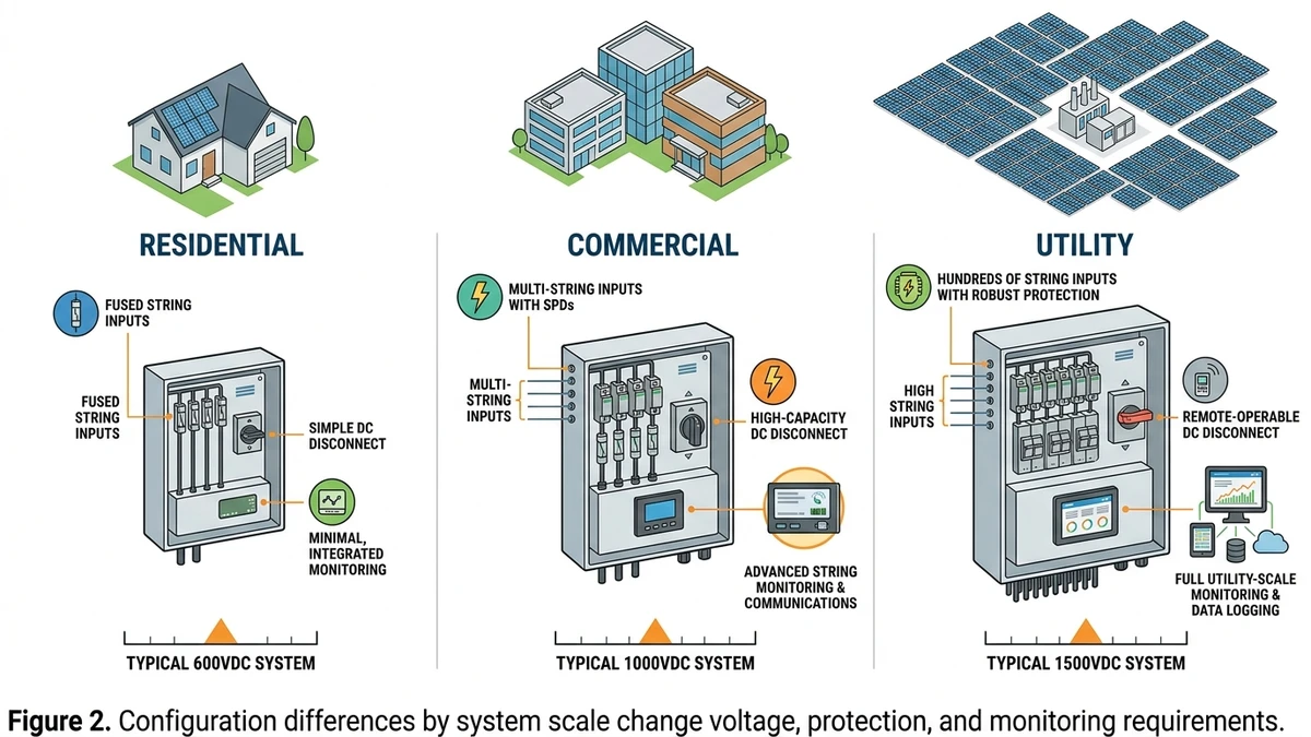
At residential scale, low string count makes faults easier to isolate, but installation quality is the main variable. Loose terminals, missing surge protection devices, and poor torque control cause a large share of failures.
Commercial systems introduce more frequent protection-selection mistakes. Using standard gG fuses instead of IEC 60269-6 rated gPV fuses is a common error because gG fuses are not designed for the sustained DC current profile of PV strings.
At utility scale, current imbalance and hidden contact degradation become harder to detect without per-string monitoring. In a 60 MW ground-mount installation in Inner Mongolia (2023), per-string monitoring showed that 8% of strings were operating more than 15% below expected current, traced to partial shading mismatches and degraded fuse contacts that visual inspection had missed. IEC 62548-1 string-level overcurrent protection becomes especially critical when 24 or more strings share one busbar.
For a deeper look at scale-specific design, the 6-string commercial combiner box design guide covers component selection across voltage tiers.
[Expert Insight]
– On rooftop systems, inspect gland compression and terminal torque first; those two points explain a disproportionate number of early-life faults.
– In commercial arrays, keep a record of actual string Isc readings after commissioning so future nuisance trips can be compared against a real baseline, not only nameplate data.
– In utility blocks, trend fuse-holder temperature by row or inverter block; relative deviation often reveals bad contacts before a fuse opens.
– If only one box in a group shows repeated alarms, compare it to adjacent boxes with the same orientation and module type before replacing parts.
| Problem # | Standard | Requirement | Common Violation |
|---|---|---|---|
| 1 — Undersized fuse | IEC 60269-6 / NEC 690.9 | Fuse rated ≥ 1.56 × Isc per string | Fuse sized to Isc only, no temperature derating |
| 2 — Missing SPD | IEC 61643-31 / NEC 690.11 | SPD required on DC circuits > 80V in lightning zones | SPD omitted or Up protection level mismatched to inverter input |
| 3 — Inadequate enclosure rating | IEC 60529 / NEC 690.31 | IP65 minimum for outdoor combiner boxes | IP54 enclosures installed in exposed rooftop locations |
| 4 — No string monitoring | NEC 690.5 (ground-fault) | Ground-fault protection on PV output circuits | Monitoring absent; ground faults undetected for weeks |
| 5 — Wrong DC breaker rating | IEC 60947-2 / NEC 690.9 | Breaking capacity rated for 1000 VDC or 1500 VDC system voltage | AC-rated MCBs substituted for DC circuit breakers |
| 6 — Loose terminal torque | IEC 60999-1 / NEC 110.14 | Terminals torqued to manufacturer spec (typically 2–4 N·m) | No torque verification at commissioning |
| 7 — Missing disconnect | NEC 690.15 / IEC 62548-1 §9 | Accessible DC disconnect within sight of combiner | Disconnect absent or non-load-break type used |
| 8 — Conductor ampacity | NEC 690.8 / IEC 60364-7-712 | Continuous current capacity ≥ 1.25 × Isc | Conductors derated for conduit fill but not for ambient temperature |
| 9 — Reverse polarity protection | IEC 62548-1 §8.4 | String diodes or fuse coordination prevents reverse current | Blocking diodes omitted in parallel string configurations |
| 10 — Labeling gaps | NEC 690.53 / NEC 690.54 | Maximum voltage, current, and polarity labels required | Labels missing or faded within 18 months of installation |
In a 35 MW ground-mount project in Hebei Province (2023), a compliance audit found that 60% of combiner boxes had fuses sized without the 1.56× Isc multiplier required under IEC 60269-6, triggering full string-level replacements before grid connection approval.
For surge protection, IEC 61643-31 requires coordination between the SPD’s Up level and the inverter’s maximum input voltage tolerance, a detail frequently missed during procurement.
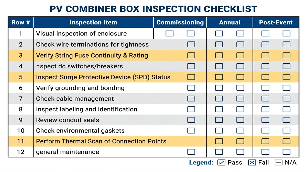
The checklist below maps common failure points to commissioning, annual, and post-event inspections so crews can catch degradation before it becomes lost yield or equipment damage.
Each row covers one inspection point. Mark Pass / Fail / N/A per column.
| # | Inspection Item | Commissioning | Annual | Post-Event |
|---|---|---|---|---|
| 1 | Enclosure IP rating intact (min. IP65 for outdoor) | ✓ | ✓ | ✓ |
| 2 | Cable entry seals and gland torque (≥ 2.5 N·m typical) | ✓ | ✓ | ✓ |
| 3 | String fuse continuity and rating match (gPV, IEC 60269-6) | ✓ | ✓ | ✓ |
| 4 | DC circuit breaker trip test and Icu rating verification | ✓ | ✓ | ✓ |
| 5 | SPD status indicator check (IEC 61643-11 Class II) | ✓ | ✓ | ✓ |
| 6 | Busbar torque check on all terminals (per manufacturer spec) | ✓ | ✓ | ✓ |
| 7 | Thermal scan of busbars and fuse holders (ΔT ≤ 10 °C vs. ambient) | — | ✓ | ✓ |
| 8 | String current balance across all inputs (deviation ≤ 5%) | ✓ | ✓ | ✓ |
| 9 | DC disconnect switch operation and contact wear | ✓ | ✓ | ✓ |
| 10 | Grounding continuity and bonding resistance (≤ 0.1 Ω) | ✓ | ✓ | ✓ |
| 11 | Moisture, corrosion, or pest ingress inspection | — | ✓ | ✓ |
| 12 | Monitoring data log review (string-level alarms, voltage drift) | — | ✓ | ✓ |
Post-event inspections apply after any lightning strike within 500 m, flooding, hail above 25 mm diameter, or a grid fault exceeding 1.2 × rated voltage. Prioritize items 3, 5, and 7 first because fuses, SPDs, and thermal anomalies are the most common casualties.
[Expert Insight]
– During annual inspections, compare torque findings against commissioning records; repeat loosening at the same point often signals conductor creep or a damaged lug, not just missed tightening.
– After a nearby lightning event, replace any SPD with a red indicator before resetting alarms, even if the rest of the box looks normal.
– Use thermal imaging near peak irradiance, not early morning, or you may miss load-related hot spots on fuse holders and busbars.
– If insulation resistance drops after rain but recovers in dry weather, suspect gland seals or condensation paths before assuming cable insulation failure.
Most combiner box failures begin upstream in design and procurement: wrong fuse class, AC-rated protection in a DC circuit, insufficient voltage rating, or enclosure hardware not suited for the environment. For 1500 VDC string architectures, verify that every fuse carries a gPV rating per IEC 60269-6 and that DC MCBs meet IEC 60898-2 breaking capacity at full rated voltage. String fuses are commonly selected at 1.5–2× module Isc to ride through normal thermal variation without nuisance opening.
Explore the full range of DC fuses sized for 1000 V and 1500 V PV systems, or review how to wire a PV combiner box correctly to confirm your layout matches your string count and fault current exposure. For surge protection, IEC 61643-11 Type 2 SPDs with Up ≤ 2.5 kV are the baseline for most ground-mount and rooftop combiner boxes.
String-level overcurrent protection is the first line of defense in any combiner box. For fuse-based systems, the gPV fuse series covers IEC 60269-6 rated devices from 2 A to 32 A at up to 1500 VDC. For breaker-based designs, the DC MCB series provides breaking-capacity data and voltage ratings relevant to fuse, breaker, and string-fault troubleshooting.
Transient overvoltage faults require SPDs rated to IEC 61643-31, with Up protection levels typically between 2.0 kV and 4.0 kV for 1000–1500 VDC systems. The surge protection device page covers selection criteria by system voltage and installation zone. For safe isolation procedures, the DC switch disconnector series details load-break ratings and lockout-tagout compatibility.
Incorrect wiring is a common cause of commissioning-stage failures. The PV combiner box wiring diagram and grounding guide covers conductor sizing, grounding conductor cross-sections, and bonding continuity requirements. For a broader installation walkthrough, the how to wire a PV combiner box guide steps through terminal torque values, polarity verification, and pre-commissioning checks.
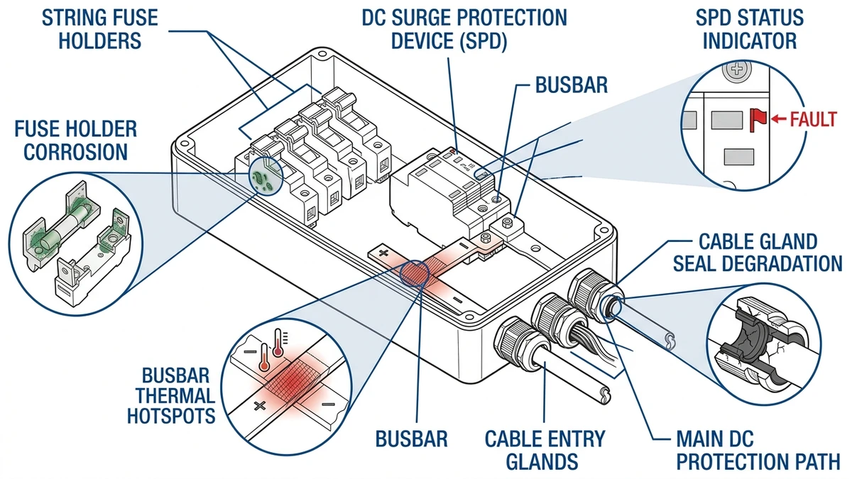
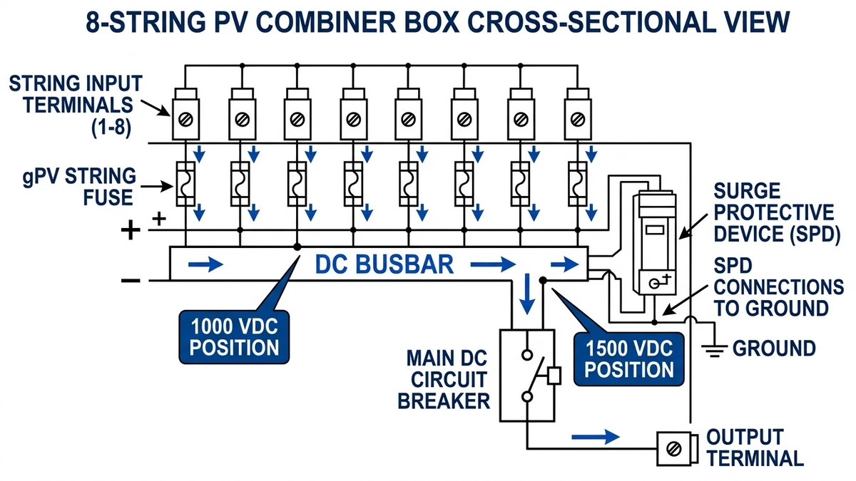
A standard combiner box routes multiple PV string inputs through individual string fuses before merging at a DC busbar. From there, current passes through a DC circuit breaker or DC switch disconnector rated for the full combined output before exiting to the inverter. Surge protection devices connect between the busbar and ground to clamp transient overvoltages.
SPD clamping voltage: Up ≤ 2.5 kV (at In = 20 kA, per IEC 61643-11 Class II)
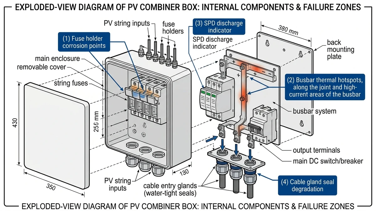
The figure below shows a labeled cross-section of a typical 8-string combiner box. Use it as a diagnostic reference: trace each string circuit from input terminal to string fuse, then to busbar, main breaker, and output. When a fault appears, that flow tells you which component to test first based on symptom location.
Overheating usually comes from loose terminations, undersized conductors, or poor ventilation that raises contact resistance and internal temperature during peak current.
Most sites should inspect combiner boxes every 6–12 months, with shorter intervals for utility-scale plants or harsh environments with dust, humidity, or frequent storms.
No. AC breakers are not designed to interrupt DC arcs reliably at PV system voltages, so DC-rated protection must be used.
A red indicator means the surge protection module has reached the end of its protective life after absorbing transient energy and should be replaced.
A low reading depends on test method and system design, but a result around or below 1 MΩ during maintenance checks generally warrants further investigation for moisture or cable damage.
Repeated fuse operation often points to reverse current, string mismatch, or an incorrect fuse rating rather than a random device failure.
Inspect SPD status first, then verify fuse continuity, breaker condition, insulation resistance, and any new thermal anomalies before returning the combiner box to service.


